Prefabricated shear wall structures are integral systems composed of precast components securely connected using cast-in-place concrete and cement-based grout on-site. The reliability of these connection nodes is crucial for maintaining structural integrity and ensuring seismic resistance. These nodes typically include beam-to-column connections, column-to-column connections, and horizontal and vertical wall connections.
Vertical Connection Methods for Prefabricated Shear Wall Structures
There are two main types:
1. Dry Connection
This method requires no concrete pouring on-site. All prefabricated components, embedded parts, and connectors are manufactured in the factory and assembled using bolts or welding.
2. Wet Connection
Wet connection involves linking the steel bars of two load-bearing components and achieving an integrated structure by pouring concrete at the nodes, simulating cast-in-place connections.
Currently, the most common method in China is the wet connection, which mainly includes cast-in-place strip connection, grouting sleeve connection, and grouting anchor connection.
1. Cast-in-Place Strip Connection
This technique involves installing precast shear walls at their designated locations, placing cast-in-place strips between the upper and lower shear walls to be connected, and passing reserved steel bars through the strips. The components are then joined using an overlap connection method, where concrete is poured after installation to form a unified structure.
Characteristics: The position of the upper shear wall can be challenging to fix accurately, and achieving sufficient concrete compaction on the top surface of the cast-in-place strip is often difficult.
2. Grouting Anchor Connection
Grouting anchor connection involves inserting the load-bearing steel bars of prefabricated components into reserved holes in the corresponding components. The gap between the steel bars and the hole walls is then filled with high-strength, non-shrinkage grouting material to anchor the bars securely.
Common anchor connection types include spiral reinforcement-constrained grout anchor connection and metal corrugated pipe grout anchor connection.
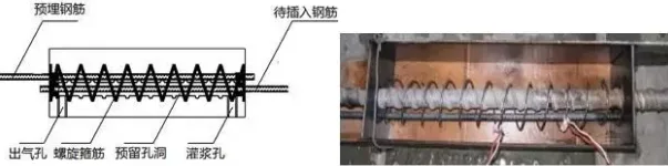
Schematic diagram of spiral reinforcement-constrained grout anchor connection.
Features: This method offers stable mechanical performance, simple operation, and ease of filling gaps between ribbed steel bars. It is particularly suitable for vertical steel bar connections.
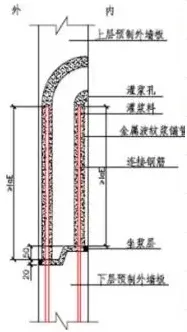
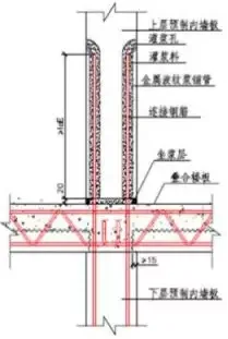
Schematic diagram of metal corrugated pipe grout anchor connection.
Interior wall panel:
Exterior wall panel:
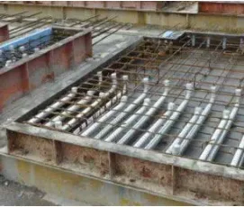
Real-life image.
3. Sleeve Grouting Connection
This connection involves inserting reserved steel bars into high-strength sleeves with concave and convex grooves. Non-shrinkage, high-strength grout is then injected between the steel bars and the sleeve’s inner cavity to form a secure connection.
Common sleeve grouting connection types include full sleeve grouting connection (for horizontal components) and half sleeve grouting connection (for vertical components).
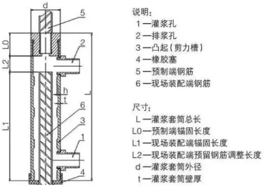
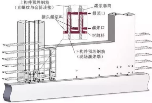
Schematic diagram of semi-sleeve grouting connection.
Characteristics: The grouting strength is comparable to that of the steel bar, effectively acting as part of the reinforcement. This method offers stable and reliable mechanical properties, short construction periods, and convenient connection operations.
Dry Connection Methods include bolt connection, post-tensioned connection, mechanical connection, welded connection, and lap joint connection.
Advantages: Dry connections simplify assembly processes, significantly shorten construction time, reduce on-site labor, ensure construction quality, and promote energy conservation and environmental protection.
Disadvantages: These connections require attention to corrosion resistance and fire protection.
1. Bolt Connection
This method uses bolts to fasten and connect structural components such as columns to columns, beams to beams, and beams to columns. Components feature bolt holes and installation handholes at their edges, through which bolts are threaded to secure the connection.
Schematic diagram of bolt connection.
Characteristics: This method features a short construction period, simple operation, and is suitable for connecting prefabricated components. It provides good bearing capacity, stiffness, shear resistance, and energy dissipation, making it a reliable connection technique.
2. Post-Tensioned Prestressed Connection
Before pouring concrete, holes are reserved in the precast shear wall based on the prestressed reinforcement layout. Once the concrete reaches the required strength, the prestressed reinforcement from the lower precast shear wall is inserted into these holes extending to the top of the upper wall. The reinforcement is anchored with end anchors, and high-strength grout is injected to bond the components into a unified structure.
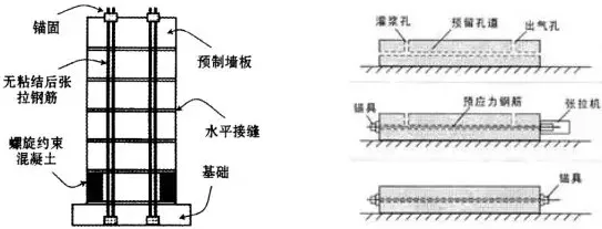
Schematic diagram of post-tensioned prestressed connection.
Features: This connection offers strong seismic resistance and enhances the frictional shear strength of component joints.
3. Welding Connection
This method connects concrete components using pre-embedded steel plate connectors through welding.
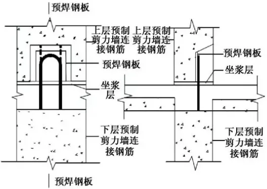
Welding connection diagram.
Features: Electric arc welding is cost-effective, simple, widely applicable, and offers excellent stress performance.
4. Mechanical Connection
Mechanical connections join two steel bars using mechanical bite action facilitated by steel bars and connectors. Common types include squeeze sleeve joints, taper thread sleeve joints, and straight thread sleeve joints.
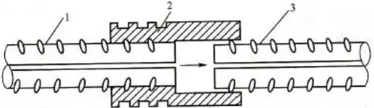
Schematic diagram of sleeve compression connection.
1. Squeezed steel bars; 2. Steel sleeve; 3. Unstressed steel bars.
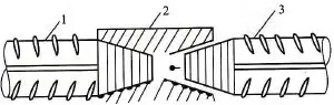
Schematic diagram of cone thread sleeve connection.
1. Connected steel bars; 2. Cone thread sleeve; 3. Unconnected steel bars.
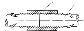
Schematic diagram of straight threaded sleeve connection.
1. Steel bars to be connected; 2. Sleeve.
Features: Mechanical connections are more reliable than welding, cost-effective, broadly applicable, and easier to operate. They are especially suited for connecting large-diameter steel bars.
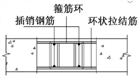
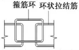
5. Overlapping Connection
This method primarily connects reserved tie bars and stirrups extending from the edges of components. The bars are tied with iron wire, vertically inserted with steel bars inside the stirrups, and then concrete is poured to form concealed columns, completing the vertical BIM building connection of prefabricated components.
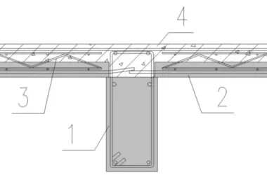
Schematic diagram of overlapping connection.
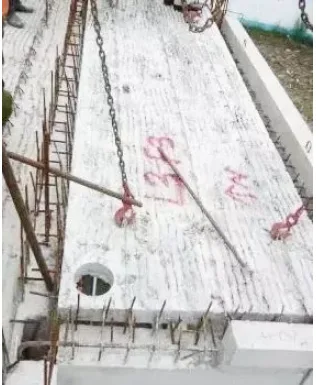
Vertical steel bar connection of shear wall.
Reinforcing bar connection.
Features: Overlapping connections are easy to construct and resistant to external factors. They do not require highly skilled workers, making them ideal for connecting smaller diameter steel bars.


Must log in before commenting!
Sign Up