Abstract: This article presents the application of BIM technology in the exterior design of the 290 Mulberry Street project in New York. Software tools were utilized to generate panel data and produce the necessary drawings and documentation.
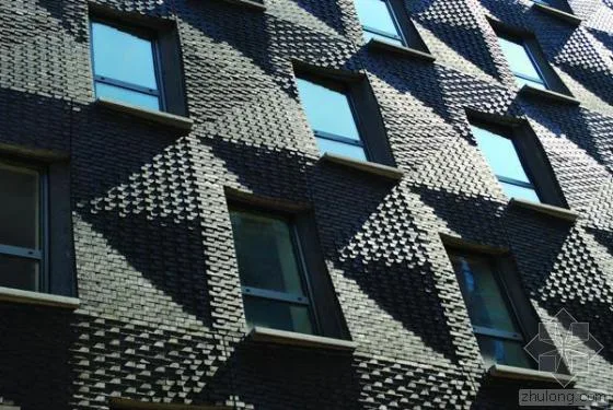
Exterior Surface Construction Effect
Challenges in Skin Design
The 290 Mulberry Street project is situated on the northwest edge of Nolita, New York, bordered by Houston Street to the north and the historic Puck Building on Mulberry Street to the west.
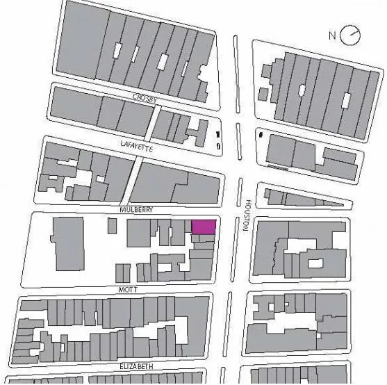
Figure 1 – 290 Mulberry Street General Plan
This 13-story building, including the rooftop equipment level, consists of commercial spaces on the first floor and basement, with nine residential units above. Each standard floor covers approximately 2,000 square feet. Given the high real estate values in this area, optimizing the facade thickness is essential to balance the added value of the skin design with the saleable interior space.
Urban zoning regulations require the building to face both Houston and Mulberry Streets using stone architecture. The exterior walls are designed to complement the adjacent Puck Building, one of New York’s most iconic stone structures, creating a harmonious relationship with the surrounding environment.

Figure 2 – A corner of the Puck Building with 290 Mulberry under construction in the foreground
The building’s context directly shapes its exterior, reflecting the architect’s response to local neighborhoods and building codes. SHoP’s design philosophy centers on interpreting local regulations alongside a contemporary reinterpretation of the Puck Building’s character, avoiding traditional mixed methods when addressing stone facades and detailing.
Transforming Challenges into Opportunities
The design of 290 Mulberry Street is driven by several key objectives: maximizing interior space, adhering to regulatory building envelope limits, and minimizing facade thickness. These criteria, combined with material properties and manufacturing constraints, inspired a modern reinterpretation of traditional brick wall detailing.
Advances in construction technology now allow for thinner walls, responding to economic pressures from the demand for larger interior areas within limited lot sizes. While traditional stone facades require thick walls to accommodate multi-layered detailing, modern methods enable slimmer profiles that preserve valuable floor area.
To address this, SHoP explored the allowable space outside the property line for decorative elements. According to New York City Building Code, projections of up to 10 square feet per 100 square feet of building area are permitted, with a maximum extension of 10 inches. This applies to prominent features such as rounded corners and eaves.
SHoP proposed a unique “Ripple” skin design, where bricks protrude and stack across the facade in a dynamic, undulating pattern—resembling rounded corners but covering almost the entire facade, slightly exceeding the property line by approximately 0.75 inches (1.9 cm). To comply with regulations, analysis software was used to calculate the average projection beyond the property line, ensuring code compliance.
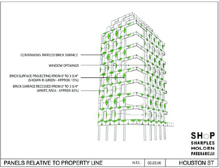
Figure 3 – Analysis drawing illustrating building skin regulation compliance
Achieving precise brick positioning on the facade manually is impractical. Instead, bricks are pre-assembled into custom panels off-site at the factory.
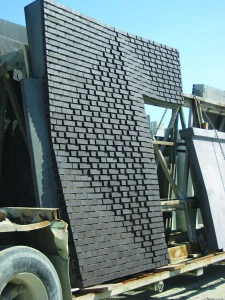
Figure 4 – Individual precast brick panel units ready for transportation
Panelized construction not only enhances design flexibility but also offers significant time advantages. Panels can be manufactured concurrently with structural work and rapidly installed on-site by cranes. This approach improves quality control and reduces exterior construction time, enabling earlier commencement of interior finishing. By leveraging digital construction technologies, architects optimized design benefits and expanded usable area with minimal cost.
The building’s exterior exhibits a rich texture facing the street, contrasting with a simple concrete frame core inside. The window-to-wall ratio aligns closely with traditional apartment buildings in the surrounding blocks, featuring staggered, perforated windows throughout. The facade’s “packaging paper” concept combines brick dynamics and consistent form to deliver a modern visual impression.

Figure 5 – Rendering from Mulberry Street looking north, showing brick exterior and concrete core
The design progresses simultaneously at two scales. At the micro scale, individual bricks protrude no more than 0.75 inches (1.9 cm) beyond neighboring bricks. At the macro scale, panel layouts coordinate precisely with the column grid, floor heights, and window openings. Using both physical and digital models, SHoP refined the design iteratively—from detailed brick arrangements to overall facade composition.
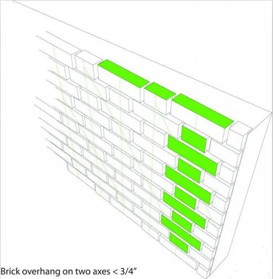
Figure 6 – Diagram illustrating the “One Line One Line” masonry method for the brick facade
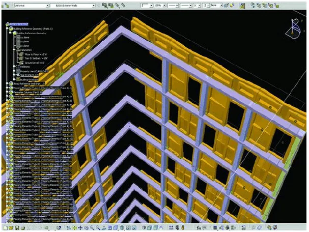
Figure 7 – Computer surface model showing coordination of window placement, panel design, and building structure
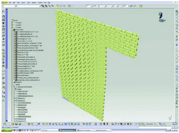
Figure 8 – Parameterized model controlling brick layout within each panel
Architects approached the building skin as a layered system rather than a predetermined form, initiating parametric digital modeling before finalizing the building’s shape. Parameterized models proved invaluable for exploring component options and manufacturing techniques within defined constraints, rather than fixed geometries. This process clarified design parameters and enabled adaptive development without suppression of creativity.
Throughout the project, iterative feedback and testing occurred across various stages. Software-based feedback loops established technical and aesthetic parameters. SHoP employed the best-fit tools for each design aspect using an open, multi-device platform. Separate digital models played a critical role in quality control by allowing thorough review of data and form.
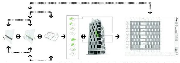
Figure 9 – Diagram of the 290 Mulberry Street feedback design program, illustrating mutual reinforcement across scales
The software tools enabled designers to quickly establish and test simple rules and implement timely adjustments. The platform was transparent, precise, and flexible enough to support evolving solutions. This project marked SHoP’s first use of Building Information Modeling (BIM) technology—a software system that integrates detailed component information and synchronizes changes across all model views.
SHoP utilized Revit, a BIM platform capable of parameterizing and coordinating data from multiple sources, to generate drawings and documents from panel data produced via various software.
Collaboration and Manufacturing
The materials and fabrication methods for the brick panels had a fundamental influence on the facade design, serving as dominant factors from the outset. Accordingly, SHoP engaged manufacturers and contractors early in the process to research production techniques and achieve required construction tolerances both within and between panels.
The key to fabricating the skin panels lies in the use of a cement lining that supports bricks during casting. This lining is a flexible rubber material developed in collaboration with manufacturer Saramac and customized to SHoP’s specifications.
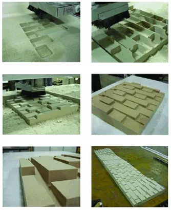
Figure 10 – CNC-produced main positive plates used to manufacture rubber lining plates
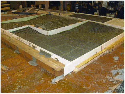
Figure 11 – Rubber lining plate cast to form individual skin panels
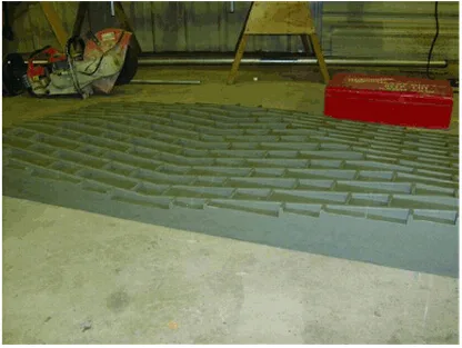
Figure 12 – Rubber lining unit with bricks placed for panel fabrication
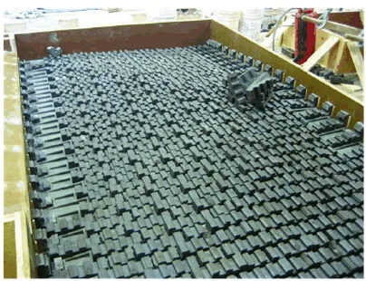
Figure 13 – Bricks positioned in rubber lining; backs mechanically fixed to the cement layer
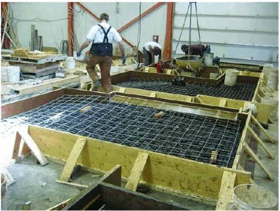
Figure 14 – Panel fixed by template during production, with bricks in lining and reinforcing steel bars; cement not yet poured
Due to the high cost of raw materials, SHoP designed the enclosure system so that every panel could be produced using the same fundamental positive plate.
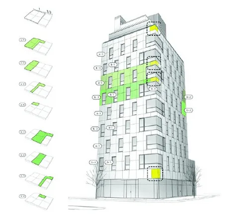
Figure 15 – Various panel types produced from the same base panel, maximizing efficiency. This approach influenced every detail of the facade, including panel-to-panel connections, window-to-panel integration, brick-to-concrete interfaces, and panel-to-structure details. The lining plate is critical for maintaining precise brick placement, joint forms, and relationships with neighboring bricks, making its accurate manufacture essential.
Value and Economy
During the design development of 290 Mulberry Street, a simple yet effective logic emerged. The architectural design achieves strong economic efficiency by integrating value parameters throughout the process. This project not only leverages digital tools but also reflects the architects’ comprehensive use of software to produce technically sound, aesthetically pleasing, economical, and beautiful results.
The integration of exterior, structural, and auxiliary building components is often the most complex and failure-prone stage in construction. BIM’s greatest advantage in this and other projects lies in facilitating early collaboration between design and construction teams. By virtually integrating all building lifecycle components through digital technology, potential problems can be identified and resolved before construction begins, rather than during the build phase.
This proactive approach maximizes building potential and overall value.


Must log in before commenting!
Sign Up