
One of the most important factors in architecture is stability. To achieve this goal, a good foundation is essential. Today, we have compiled the detailed construction points of earthwork and foundation. Let’s take a look together.
earthwork
1. Soil nail wall – foundation pit support
The specific quantity, length, position, and mesh requirements of soil nails shall be determined based on professional design calculations. The length of soil nails should be 0.5-1.2 times the excavation depth, with a spacing of 1-2m and an angle of 5-20 ° with the horizontal plane; Soil nail reinforcement should use HRB335, HRB400 grade, with a diameter of 16-32mm, and a drilling diameter of 70-120mm; the grouting strength grade should not be lower than M10. The concrete grade of the surface layer should not be lower than C20, and the thickness of the steel reinforcement protective layer should not be less than 20mm.
The construction sequence is: slope repair → drilling → installation of soil nails → grouting → binding of mesh and reinforcement bars → shotcrete. Soil nail support should be constructed under the condition of eliminating groundwater. The horizontal distance of the concrete sprayer should not be less than 100m, and the vertical distance should not be less than 30m. The air compressor should have an air flow rate of 9m ³/min or more, and the conveying pipe should be able to withstand a pressure of 0.8MPa or more.
2. Grouting pile – foundation pit support
The specific pile diameter, pile length, embedded depth, reinforcement, etc. are determined based on design calculations. The pile diameter of cantilever structure should not be less than 600mm. A reinforced concrete crown beam connection should be installed at the top of the pile, and the width (horizontal direction) of the crown beam should not be less than the pile diameter, and the height (vertical direction) of the crown beam should not be less than 400mm. The concrete strength grade of the pile and the top crown beam of the pile should be greater than C20; When the crown beam is used as a connecting beam, it can be reinforced according to the structure.
The construction sequence is: drilling holes with a drilling rig → hoisting steel cages → pouring concrete → crown beam construction. The allowable deviation for pile position is 50mm, and the allowable deviation for verticality is not more than 0.5%. The reinforcing hoop reinforcement and main reinforcement are welded by electric welding, while the spiral hoop reinforcement and main reinforcement are connected by binding.
3. Anchor pulling – foundation pit support
The specific number, diameter, length, position, and embedding depth of anchor rods shall be determined based on design calculations. Anchoring can be combined with pile arrangement. It can also be used in combination with soil nail walls.
The construction sequence is: drilling rig drilling → anchoring → grouting → curing → anchor installation → anchor rod tensioning. The allowable deviation of the hole position shall not exceed 100mm; the deviation shall not exceed 3%; The anchorage section must have a strength greater than 15MPa and reach 75% of the design strength before it can be tensioned. The anchor rod is anchored between the piles, and the anchoring force is transmitted to the pile body through the steel waist beam.
4. Internal support of foundation pit – foundation pit support
For pile and slab wall support structures, when the depth of the foundation pit is greater than the BIM tutorial, support points need to be added to maintain reasonable wall stress and control deformation. Setting up supports inside the pit is called internal support; Pulling support outside the pit is called anchoring. Internal support usually includes steel structure support and reinforced concrete support. Before dismantling the support, reliable replacement support transmission components or backfill compaction should be installed between the main structure and the support.
Steel structure support requirements: The connection of steel structure support components can be made by welding or high-strength bolt connection; The waist beam connection node should be set near the support point and should not exceed 1/3 of the support spacing; The steel waist beam should be filled with not less than C20 fine aggregate concrete between the pile and the underground continuous wall; The connection nodes between steel waist beams and steel supports should be equipped with stiffeners.
Requirements for reinforced concrete support: The concrete strength grade of the component should not be lower than C20; The support system should be poured as a whole in the same plane, and the waist beam connection points at the corners of the foundation pit plane should be designed as rigid nodes. The selection, layout, cross-section, and node connections of internal supports must be strictly designed.
5. Layered paving of backfill soil – manual backfilling
The thickness and number of compaction passes for filling layers should comply with the provisions in the table above. When backfilling in sections, each layer at the joint should be staggered by more than 1m. The thickness of each layer of backfill soil during winter should be reduced by 20% to 25% compared to normal construction, with frozen soil content not exceeding 15% and particle size not exceeding 150mm. The particle size of backfill soil at room temperature should not exceed 50mm.
6. Backfilling at pipeline location – manual backfilling
Due to the limitations of the pipeline below, mechanical compaction is no longer possible, and manual compaction is used to compact and compact from below the pipeline; Manually compact both sides of the pipeline and within 500mm above it to avoid damaging the pipeline. Mechanical compaction should be used normally 500mm above the pipeline. During winter, backfill soil containing frozen soil shall not be used within a range of 0.5m from the bottom of the trench to the top of the pipe.
7. Earthwork excavation – mechanical excavation of soil
Before excavation, a soil excavation map should be drawn first. The excavation plan should indicate the upper and lower opening lines of the foundation pit, the edge lines of the cushion layer, the edge lines of the foundation, the elevation of the base, the upper and lower opening lines of the deep excavation section, and the plane positions of all lines.
When the slope protection form is soil nail wall, a combination of small and large steps excavation method is usually used. Taking 2 large steps and 6 small steps as an example, first, complete the excavation of 3 small steps, and then complete the excavation of 1 large step towards the central area; Then, complete the earthwork excavation below in this order, leaving a 300mm soil layer; Finally, manually clear the soil to the bottom of the trench. The thickness of each layer is determined based on the actual site conditions and the design scheme of the soil nail wall. Winter construction must prevent the soil under the foundation from freezing, and loose soil or covering should be reserved.
 Foundation and Base
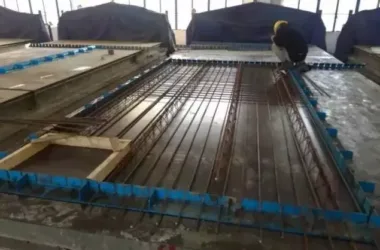
1. Retention of foundation raft slab pouring strip
1. Materials
Steel plate waterstop, steel plate mesh, wooden formwork, steel bars.
2. Process method
According to the thickness of the raft and the position of the waterstop, weld additional steel bars with a diameter of Φ 12 at the center along the length direction of the waterstop steel plate, with a spacing of 300-500mm.
Connect the additional steel bars to the upper and lower steel bars of the raft to fix the waterproof steel plate, and the groove of the waterproof steel plate should face the upstream surface. Cut the steel mesh according to the position of the water stop steel plate and the thickness of the raft, and install the steel mesh at the upper and lower parts of the water stop steel plate. The steel mesh is located inside the additional steel bars and tied to the raft steel bars.
Set up a template on the outer side of the steel mesh, and saw a groove at the top of the template according to the spacing between the steel bars. Control the thickness of the steel bar protection layer and the spacing between the steel bars, and the spacing between the supporting and reinforcing square timber should not exceed 500mm.
3. Quality requirements:
The allowable deviation for the width of the post pouring strip is ± 10mm, and the water stop steel plate is fixed straight.
2. New waterproofing screw for basement exterior wall
1. Materials
Template, waterproof screw, dry and hard waterproof mortar, expansion agent, cement-based waterproof coating.
2. Process method
Set up the inner formwork of the basement exterior wall according to the template control line. Drill holes on the template, avoiding the steel bars at a distance of 400-500mm, and install a new type of middle waterproof screw that can be disassembled and reused at both ends. Drill holes at the corresponding position of the outer mold screw and install the outer mold. Concrete shall be poured in layers, with each layer having a thickness not exceeding 600mm.
Loosen the nut and remove the reinforcement material for the template. Use a wrench to remove the reusable parts at both ends of the screw and remove the template. Clean the debris inside the hole with a cylindrical brush and spray water to moisten it 3 hours before construction. Fill the slightly expanded dry and hard waterproof mortar flush with the wall surface. Brush a layer of cement-based waterproof coating on the surface and water it for at least 3 days of curing.
3. Quality requirements:
The ends of the bolt holes are tightly packed and waterproofed in place.
3. Construction of cast-in-place piles without excavation of soil between piles
1. Materials
concrete.
2. Process method
Before pile foundation construction, excavate the soil to the bottom elevation of the cushion layer and construct the concrete cushion layer. The method of first constructing the cushion layer and then constructing the piles (which can effectively control the length of the virtual pile and avoid excavation between piles) generally requires a cushion layer thickness of not less than 200mm, and the top elevation of the cushion layer should be 100mm lower than the design pile top elevation. On the completed cushion layer, snap lines one by one to locate the engineering piles, and the setting out size should be 50mm larger than the pile design size.
After using a cutting machine and an air pick to remove the concrete layer inside the laying line, a pile top formwork (150-200mm higher than the design pile top elevation) is erected. The pile foundation concrete is poured to the top surface of the formwork. During pouring, vibration should be strengthened at the pile top position to eliminate the floating slurry of the top concrete. Dismantle the template BIM and clean the surface of the pile top and concrete cushion layer to meet the requirements of waterproof construction base.
3. Quality requirements
The allowable deviation of pile top elevation is+20mm, -30mm, and the deviation of pile position is ± 30mm.
4. Prefabricated cover plate sealing for shear wall post pouring strip
1. Materials
Waterproof mortar, prefabricated cover plate, waterproof roll material.
2. Process method
The post pouring strip of the basement shear wall can be constructed by using prefabricated cover plates for sealing and early backfilling. The sealing cover plate should have a width not less than 200mm wider than the post pouring strip and a thickness that is waterproof and resistant to lateral pressure from backfill soil.
The contact area around the pouring strip before and after installation should be cleaned thoroughly, and the waterproof membrane at the root should be protected.
After leveling, the first cover plate should be lifted and installed manually or with an electric hoist. The pre embedded steel bars of the cover plate should be firmly welded to the steel bars of the post pouring strip. The cover plate should be fully grouted with the base layer and between each other, and prefabricated cover plates should be installed sequentially to the top of the shear wall. The surface of the cover plate is compacted and leveled with waterproof mortar.
3. Quality requirements
The prefabricated cover plate is installed firmly and waterproof reliably.
5. Construction of super large area concrete foundation slab using the jumping method
1. Materials
Ready mixed concrete, formwork and support components, and collapse closure net.
2. Process method
During the construction of large-area foundation concrete raft slabs, in order to effectively control the internal temperature rise of the concrete and prevent cracks, the method of pouring concrete by dividing the length and width directions into separate compartments can be adopted.
The division of compartments should be determined based on the thickness of the raft, structural form, engineering quantity, labor force, etc. Generally, the length of the compartments should not exceed 30m. When pouring concrete, the construction can be carried out in a staggered manner according to the “product” character. The construction inside each compartment should be carried out in layers according to thermal calculations, and no construction joints should be left after one pouring is completed; The pouring of adjacent concrete should be carried out after the strength of the previous concrete meets the requirements, and quick closing nets should be installed at the construction joints to prevent concrete from spilling.
During the concrete pouring process, temperature measurement points and facilities should be buried in advance, with surface coverage and curing meeting the requirements, and the temperature difference should be controlled within 25 ℃.
3. Quality requirements
The concrete is compacted and compacted without any cracks.
6. Waterproof joint treatment of foundation root roll material
1. Materials
Waterproof membrane and adhesive.
2. Process method
The base roll material is laid first on the flat surface, and then on the vertical surface. The dimension of the flat roll extending beyond the outer edge of the foundation shall not be less than 300mm, and the length of adjacent rolls shall be staggered, with a staggered dimension of not less than 300mm. After the completion of the concrete foundation construction, when laying the facade roll, the internal and external corners should be rounded corners with a diameter greater than 50mm. The joint part of the roll should be uncovered and cleaned, and the damaged parts should be repaired. The adjacent joints and upper and lower layer joints of the facade roll material should be staggered by no less than 300mm, and the overlapping length of the synthetic polymer roll material should not be less than 100mm. When laying, the upper part of the roll material joint should be pressed against the lower part, and a waterproof additional layer should be provided at the top joint of the raft guide wall.
The protective layer should be promptly laid in place to prevent scratching the waterproof layer.
3. Quality requirements
The waterproof membrane is firmly and tightly laid.
Article source: Architectural Technology Magazine


Must log in before commenting!
Sign Up