During the construction of building engineering projects, managing the dewatering of an entire rock foundation can be challenging. Due to the impermeability of rock foundation structures, water infiltration follows the direction of rock fissures. When these fissures are extremely close together, groundwater cannot be discharged effectively. In cases where there are many stone joints, replacing and filling the entire foundation is a viable method. However, if the rock foundation has few joints causing localized water accumulation, replacing the entire foundation leads to high costs. To address this, an analysis of the cost of small pipe dewatering technology in several projects concludes that this method is more economically feasible.
Characteristics of the Construction Method
(1) Localized seepage treatment saves significant manpower, materials, and costs.
(2) It shortens the construction period and improves efficiency.
(3) Effectively lowers groundwater levels, keeps the foundation dry, and does not impact other construction processes.
(4) Material selection is straightforward, construction technology is simple and feasible, with low technical requirements.
Scope of Application
This method applies to all rock foundations, especially high-density, impermeable foundations with cracks and water seepage issues.
Process Principle
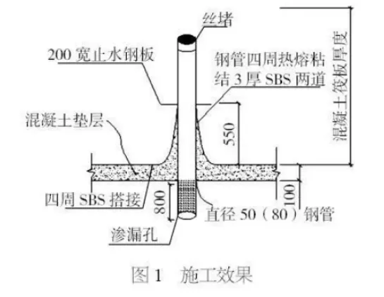
The process involves connecting cracks in the impermeable rock foundation to a prefabricated housing and inserting them into a diversion channel. The stone joints in the rock foundation are disrupted and guided into a collection pit via the diversion channel. A steel conduit buried in the collection pit is connected to a pump pipe, which drains the accumulated water from the foundation pit.
Construction Process and Operation Points
Process Flow:
Positioning and layout → foundation pit excavation → observation and analysis of water seepage areas → mapping water seepage zones → planning layout and quantity of collection pits → determining number, spacing, width, and depth of diversion trenches → excavation of collection pits and diversion trenches → backfilling with 40-60mm gravel and rubble filter → fabricating and installing water conduit sleeves → laying isolation layers → laying cushion concrete → constructing other foundation structural layers.
Key Operating Points:
(1) Determine the layout of collection pits and diversion channels based on the seepage direction of the rock foundation.
(2) Collection pits and diversion channels must have adequate width and depth to reduce precipitation below the foundation elevation by 500mm.
(3) Water conduits should be steel pipes with a minimum diameter of 80mm, welded with waterproof steel plates.
(4) Filter pipes can be made from PVC for ease of drilling and permeability.
(5) Backfill stone particle size should be no less than 40mm to prevent poor permeability or blockage around filter pipes.
(6) An impermeable isolation layer must be installed between the upper part of the water channel and collection pit and the cushion layer to prevent upward water penetration.
(7) Cone-shaped concrete should be used to fix the base around the water diversion conduit to facilitate waterproof layer construction.
Multiple collection wells can be installed in rock foundation pits where seepage occurs, depending on drainage needs. Each collection well should be at least 1.0m × 1.0m × 1.5m. The upper 500mm of each well is filled with 40-60mm crushed stones for filtration, while the lower part is filled with small rubble pieces to enhance water mobility and storage. All water conduit sleeves below the cushion layer should be drilled for permeability. A 5mm thick waterproof steel plate (200-400mm wide) is welded to the cushion layer at a minimum distance of 550mm. Waterproof roll materials are sealed at the waterproof steel plate location. The water conduit is buried in the collection pit and connected to an inlet pipe with a self-priming pump that continuously pumps water out until the raft foundation is fully poured. When pouring the concrete raft, leave a 20cm × 20cm × 20cm opening at the slab top for secondary pouring. After pouring, seal the water collection well casing tightly with anti-seepage concrete of one strength grade higher, mixed with an expansion agent. The detailed water conduit layout is illustrated in Figure 1.
Materials and Equipment
(1) Sufficient 40-60mm crushed stone, multiple rubble pieces under 300mm, 80mm diameter water conduits, waterproof steel plates, and several PVC filter pipes to meet drainage requirements.
(2) Air picks, shovels, hammers, and chisels for grooving.
(3) Additional equipment includes water pumps, pumping pipes, drainage pipes, wiring, power supply, and pump switches.
Quality Control
Once the foundation pit excavation for prefabricated buildings is complete, the drainage construction plan should be finalized based on the pit’s permeability. After plan approval, technical preparations and safety disclosures must be conducted with relevant personnel. Construction technicians, surveyors, and quality management staff must fully understand the construction plan, process flow, and terrain, as well as the pipe drainage principles. Strict supervision is essential to ensure quality at every stage. Responsibilities should be clearly assigned with defined rewards and penalties, combining supervision, guidance, construction, and inspection per regulations. The number, direction, width, and depth of collection pits and diversion channels must be planned according to the actual site conditions and foundation structure. Technicians should carefully design and execute excavation dimensions to ensure the water level is maintained at least 500mm below the foundation elevation. All technical and quality control measures set by the project department must be implemented thoroughly. Technical data should be collected, organized, classified, and archived diligently during construction.
Safety Measures
Safety is paramount, and prevention is key. Before construction begins, comprehensive preparations, including technical and safety briefings, must be completed. Relevant safety regulations must be strictly enforced to eliminate accidents, illegal commands, and unsafe operations. All personnel must wear safety helmets on site; anyone not complying is prohibited from entering. Red warning lights should be installed at night, and throwing objects into the foundation pit is strictly forbidden.
Article source: Architectural Technology Magazine


Must log in before commenting!
Sign Up