In recent years, the country has actively promoted the development of prefabricated buildings, supported by relevant policies introduced by local governments. However, many organizations remain unfamiliar with or misunderstand prefabricated buildings, which has created obstacles to their advancement. This article explores common challenges encountered during the design process and offers practical solutions applicable at the current stage.
Several issues arise in the structural design of prefabricated buildings, including:
- Reinforcement protective layer concerns
- Stress analysis of composite panels
- Stiffness amplification issues in composite beams
- Design of prefabricated exterior wall structures
- Demoulding design considerations
- Design of lifting points
- Key factors when determining splitting dimensions
Reinforcement Protective Layer Concerns
The thickness of the protective layer in cast-in-place reinforced concrete structures is typically measured from the stirrups surrounding the load-bearing steel bars. While the design unit usually completes the structural design, the component manufacturing is handled by the component processing factory. Those responsible for dismantling often apply one of three approaches regarding the column protective layer thickness:
- Strictly adhering to the design unit’s requirements, keeping the concrete protective layer thickness unchanged. However, this may result in an insufficient protective layer around the sleeve within the concrete, compromising anchorage and durability.
- Shifting the sleeve inward, which reduces the structural height (h) used in calculations, weakening load-bearing capacity and posing safety risks.
- Artificially increasing component dimensions while maintaining the position of stressed steel bars, which alters structural stiffness and leads to inaccurate calculations.
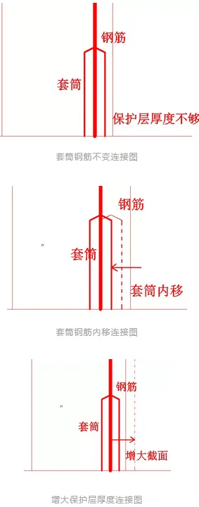
Since design and production are separate processes, designers often overlook sleeve sizing, leading to protective layer issues in actual components and potential safety hazards. Early in the design phase, designers should consider not only cast-in-place requirements but also practical manufacturing constraints.
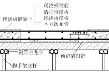
Load Analysis of Composite Panels
Composite floor slabs typically consist of cast-in-place and prefabricated sections. Designs are usually categorized as unidirectional or bidirectional slabs, depending on joint structures, support configurations, and aspect ratios. For example, the floor slab of a certain room is illustrated below:
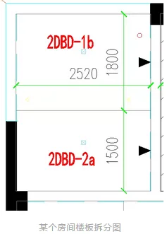
This floor is divided into two unidirectional joint slabs. Given its classification as a unidirectional slab, unidirectional load guidance is applied during design, as shown below:
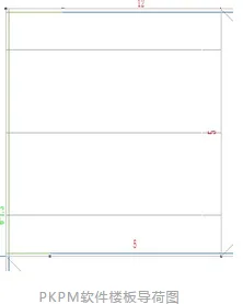
With room dimensions measuring 3300mm in length and 2520mm in width, and a 70mm cast-in-place layer atop the floor slab, the slab should actually be classified as a two-way slab based on its length-to-width ratio. Although a dense joint exists in the middle, load calculations must follow two-way slab principles rather than the manually assigned one-way slab method.
Discrepancies in load calculation methods can significantly affect the results for surrounding beams. If these differences are overlooked during design, they may lead to serious safety risks.
Stiffness Amplification in Composite Beams
When calculating internal forces and displacements, floor beam stiffness is typically amplified by factors ranging from 1.5 to 2.0 depending on flange conditions, while edge beams have amplification factors between 1.2 and 1.5.
According to the Code for Design of Structures, composite floor slabs must account for increased internal forces and displacements due to composite action. Central beams may use an amplification factor between 1.3 and 2.0, depending on flange conditions, while edge beams use factors from 1.0 to 1.5. Generally, the amplification factor should not exceed 1.8 for central beams and 1.2 for edge beams.
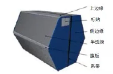
Prefabricated Exterior Wall Structure Design
Prefabricated exterior wall panels are classified based on their building location into beam-type, column-type, and wall-type panels. Beam-type and column-type panels are load-bearing components that also function as beams or columns, not merely as enclosures.
Wall-type exterior panels are non-load-bearing enclosure components, attached to the main structure similarly to curtain walls and connected via connectors.
Wall-mounted prefabricated panels are further divided into point support and line support types based on connection methods. Point support panels are classified by their degrees of freedom at connection nodes into translational or rotational types.
Non-load-bearing prefabricated exterior wall panels only carry their self-weight, wind loads, seismic loads, and construction phase loads. Under these conditions, the panels must meet the following requirements:
- At ultimate bearing capacity limit states, the panels’ ultimate capacity and deformation must comply with specifications.
- Under normal service limit states, out-of-plane deflections and crack widths must be within allowable limits.
- Connections must possess adequate load-bearing capacity and accommodate interlayer deformations, maintaining stiffness during normal use and flexibility under ultimate loads.
- Wall panel connections should be reliably attached to the main structure with straightforward force transfer and clear force distribution. Flexible connections are preferred, using either point or line connections.
Demoulding Design
During demoulding, components and lifting equipment bear loads from the mold’s adhesion to the concrete and the components’ self-weight under dynamic effects. When verifying demoulding for prefabricated components, the equivalent static load should equal the product of the component’s self-weight standard value and the sum of the dynamic coefficient plus the mold adhesion force. This value should be no less than 1.5 times the component’s self-weight standard value.
There are three typical types of lifting points used for PC components during demoulding:
- The same lifting points used during installation;
- Using truss bars or scaffolding bars;
- Dedicated lifting points specifically designed for demoulding.
In practice, the first two methods are more commonly employed, either by using the installation lifting points or by leveraging truss or scaffolding bars.
Lifting Point Design
The hoisting of prefabricated components is a critical step in the structural construction process. Due to unstable centers of gravity, components may descend too rapidly, causing them to sway and potentially detach due to centrifugal inertia forces. Poor selection of lifting points can irreversibly impact component quality and lifting safety management.
Factors to Consider When Splitting Dimensions
When dividing prefabricated components, several factors must be considered:
- Transportation and construction convenience: Components are transported by trucks, which limits their size—typically around 2.5 meters wide—due to road conditions. Construction activities such as lifting and flipping also impose limits on size and weight.
- Production feasibility: Regional component factories have limited production capacity and high mold costs. Thus, the splitting process must consider both practical manufacturability and economic efficiency.
The disassembly design of prefabricated components is foundational, determining the feasibility and ease of subsequent stages. Effective splitting can significantly improve efficiency. The division of structural components—columns, beams, walls, slabs—should adhere to principles of reasonable stress distribution, simple connections, easy construction, minimal specifications, versatile combinations, and the ability to assemble into various structural systems.
Key guidelines include:
- Maintain uniform cross-sectional dimensions for prefabricated beams, using large straight bars and fewer reinforcement types.
- Ensure symmetrical reinforcement at both ends of prefabricated shear wall edge components.
- Modularize prefabricated walls with bay windows, balconies, air conditioning panels, and stairs as much as possible.
- Modularize or evenly divide floor slabs wherever feasible.


Must log in before commenting!
Sign Up