In recent years, suspended structures have become a crucial architectural form for super high-rise and large public buildings. Their unique shapes and structural designs offer diverse possibilities for building extensions. However, due to the stringent acceptance criteria for cantilever structures, even minor deviations during construction often require rework and adjustments. So, how can we avoid the quality pitfalls commonly encountered in cantilever construction?
Pre-Construction Phase
1. Insufficient Structural Stress Optimization
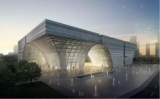
Before construction begins, it is essential to complete structural stress optimization using computer software based on the design drawings. The longer the cantilever, the greater the structural stress it experiences. For instance, the new CCTV building features an overhang of approximately 70 meters, necessitating repeated structural optimization calculations to identify potential overturning risks.
Failure to properly optimize structural stress before construction may lead to costly demolition and reconstruction during complex projects. Ignoring proper acceptance procedures can also pose significant safety hazards, seriously affecting the wellbeing of occupants.
Common issues in structural optimization include:
(1) Inaccurate Modeling Data
Parametric modeling using computer software is crucial for managing complex structural designs. It assists architects in controlling building forms and supports structural engineers in various calculations.
Errors in modeling data—often caused by delayed communication of design changes, limited team expertise, or data entry mistakes—can lead to inaccurate simulations, making it impossible to reflect the actual stress conditions of the structure. Notably, many of these problems stem from management shortcomings rather than technical faults.
(2) Improper Choice of Modeling Software
Although many software tools are available for structural modeling, selecting the right one is critical to accurately simulate and identify structural issues. Commonly used software includes:
PKPM: Particularly effective for multi-story and high-rise buildings, PKPM excels in quick reinforcement design and drawing production. It has some spatial modeling capabilities but remains less convenient compared to foreign software like ETABS, which introduced more advanced features.
3D3S: This software supports calculations for light steel, factory buildings, multi-story and high-rise structures, spatial steel frameworks, and cable membrane structures, all verified against Chinese standards.
ETABS: Designed for multi-story and high-rise structures, ETABS has revolutionized domestic structural analysis by enabling elastic-plastic and dynamic analyses, rapid modeling, and compliance with Chinese standards. It meets nearly all structural engineering requirements.
SAP2000: Focused on spatial structures such as mesh shells and irregular frameworks, SAP2000 complements ETABS by handling models ETABS cannot. It has significantly influenced spatial structure modeling and analysis in China.
Finite element software is widely used to optimize structural stress, enhancing overall construction quality. The optimization process generally involves the following steps:
(1) Refining Design Concepts
Using ABAQUS software to optimize a reinforced concrete truss structure begins with establishing an initial model. The goal is to ensure the structure meets strength and stiffness requirements while minimizing steel and concrete use to reduce costs. This involves selecting appropriate design variables, state variables, and optimization objectives, followed by reviewing the analysis results.
(2) Optimization Process and Analysis
The initial design is parameterized and modeled, followed by solving and processing results to define design variables and objectives. The optimization loop continues until the goals are achieved.
Due to structural complexity, some components may be simplified without affecting internal forces or displacements. For example, the largest cantilever beam is selected as the focus, with elements like concrete solids and steel trusses modeled. Material parameters, such as C30 concrete grade and corresponding elastic moduli, are incorporated based on the initial design.
2. Insufficient Construction Review
Effective construction review is vital for cantilever structures due to their unique shapes. Sub-projects must be adjusted accordingly, and inadequate review can cause cascading issues if design changes fail to meet requirements. Thus, thorough reviews during team planning and drawing approval stages are essential.
(1) Construction Team Review
The construction organization design profoundly impacts on-site management efficiency. Early-stage preparations require meticulous review of project information, including key challenges and engineering characteristics, ensuring alignment with field conditions.
Reviewers should verify the feasibility of construction methods, the breakdown of the organization design into stage-wise progress plans, and the inclusion of quality management and assurance measures targeted at critical cantilever construction points.
Additionally, the completeness of acceptance and handover procedures, reporting systems, process systems, and document/material storage and transfer systems should be examined.
(2) Drawing Review
Upon receiving construction drawings approved by review agencies, the construction team must perform a comprehensive and detailed familiarization and review prior to design disclosure. Emphasis should be placed on drawing layout, annotations, seismic design, and other construction-related details during joint reviews.
3. Insufficient Technical Disclosure
Technical disclosure profoundly influences construction quality. Ideally, it should occur progressively with ongoing supervision. However, the large scale and volume of cantilever projects complicate construction management, often resulting in gaps and inadequate disclosure implementation during major building projects, adversely affecting quality.
So, what level of disclosure is necessary? Which processes demand detailed specifications? Using reinforcement, formwork, and concrete as examples, technical disclosure should include the following:
(1) Reinforcement Construction
Begin by placing the main reinforcement of beams on the bottom formwork. For cantilever beams with embedded bolts, these must be installed prior to tying the hoop reinforcement, which is then secured according to bolt positions.
Key specifications include:
- Single-sided lap welding length of steel bars: 10×d (where d is bar diameter)
- Anchorage length of beam reinforcement: 40×d
- Permissible overlap sections for stressed steel bars: upper steel bars at mid-span (1/3 section), lower steel bars at supports (1/3 section)
- Welded joints within the same component should be staggered
- Welded joint length for longitudinal stressed bars: 35×d; the larger diameter bars must have at least 500mm overlap
- Within a connection section, welded joints should not exceed 50% of the longitudinal stressed steel bar area
- Hooks must be added when two or three rows of load-bearing steel bars are installed on beams
- All reinforcement must comply with design drawings, maintaining a protective concrete cover thickness of 35mm
(2) Formwork Construction
Set beam edge positions based on control axes. Before formwork installation, ensure all embedded parts are properly placed.
Secondary beam keels should use 50mm × 100mm square timber spaced at 100mm, while main keels use 48mm × 3.5mm steel pipes spaced at 300mm.
After installing the beam bottom formwork, tie the steel bars of the frame beam.
Install the beam side formwork: secondary keels made from 50mm × 100mm square timber spaced at 100mm, vertical main keels arranged with 48mm × 3.5mm steel pipes spaced at 300mm, connected at the bottom with fasteners. Two horizontal main keels spaced at 300mm are fixed with Φ12 tension bolts spaced at 600mm.
Once primary and secondary keels are installed, add steel pipe diagonal supports midway and at the bottom on both sides of the beam, spaced at 1000mm, supported by external scaffolding. Top supports should be installed at both ends of the steel pipes.
After reinforcement, cut a wooden arch at the bottom of the beam with a height equal to 0.3% of the span. Finally, adjust formwork positioning with control lines and verify verticality using plumb lines.
(3) Concrete Construction
During concrete pouring, consider the height of central columns. The number of pours for frame columns should follow the construction plan, with frame beams typically poured twice as needed.
Follow the “fast insertion and slow withdrawal” principle during concrete vibration, vibrating each point for about 10 seconds or until no slurry floats on the surface and the concrete remains stable. Remove any floating slurry to maintain the required protective layer thickness over reinforcement.
Reinforcement workers and carpenters should be present during pouring to reinforce formwork and adjust reinforcement positioning as needed, ensuring the quality of cantilever concrete placement.
During Construction

1. Insufficient Anti-Overturning Capacity
Suspended structures maintain stability through compressive weight or external tension. Design calculations consider the rotation point (O) along the outer wall skin direction, ensuring the anti-overturning moment is at least 0.8 times greater than the overturning moment. This guarantees a safety factor of no less than 1.25.
If the stability moment falls below the overturning moment, the structure becomes unstable and risks collapse. Insufficient weight on the canopy beam (such as inadequate brick height) means removing supports and formwork can lead to collapse and potential casualties.
2. Improper Formwork Support Scheme
The root of a cantilever structure endures the greatest force. If concrete at the root has not reached sufficient strength, formwork support settlement can cause immediate cracking. Premature formwork removal often leads to fractures and collapse originating at the root.
If the cantilever has a variable cross-section but the formwork is constructed with a uniform shape, root cross-section reduction may occur, increasing collapse risk after demolding.
To prevent formwork column sinking, consider the following:
- Do not support columns on soft ground or untreated backfill soil;
- Ensure pads under columns have adequate area and rigidity;
- Monitor dynamic forces after vibration;
- Prevent column sinking during thawing;
- Avoid water accumulation that could cause subsidence.
Additionally, account for the impact of moisture-induced expansion and shrinkage of wooden formwork on component quality when supporting cantilever formwork.

3. Improper Placement of Main Reinforcement
Unlike typical beam slabs, suspended components experience negative bending moments under vertical loads, causing tension on the upper side of the cantilever beam. Therefore, the main tensile reinforcement must be placed on the upper side.
Incorrect placement—such as positioning steel bars below, stepping on bars causing deformation, pressing concrete beneath the bars, insufficient anchorage length, or inadequate section thickness (especially at the root)—reduces the effective cross-section and bearing capacity. This compromises the component’s ability to support its own weight and loads above, often resulting in root collapse upon formwork removal.
4. Construction Overload
The fixed-end bending moment in a cantilever structure is directly proportional to the applied load. Exceeding the design load during construction causes formwork to settle and root cracks to appear, especially when pouring concrete outward from the root.
Excessive load leads to formwork deformation and increased cracking at the root, heightening the risk of fracture after demolding.
5. Premature Demolding
Many cantilever collapses result from early demolding and insufficient concrete strength. Regulations require that cantilever components reach 100% of demolding strength before formwork removal.
During construction, timely strength verification is crucial to determine the appropriate demolding time. Whenever possible, delayed formwork removal or partial support retention at intervals is beneficial to maintain structural integrity.
Article source: Architectural Technology Magazine


Must log in before commenting!
Sign Up