catalogue
1. Reinforcement Engineering
2. Formwork
3. Concrete Engineering
4. Masonry Engineering
5. Special Projects
1. Reinforcement Engineering
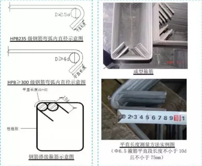
1.1 Processing of Stirrups
Basic requirements:
1. The hoop reinforcement’s formed size should be reduced by twice the thickness of the steel reinforcement protective layer from the beam or column’s cross-sectional size.
2. The bending angle at the hoop reinforcement’s end must be at least 135°, with a straight section length of no less than 5d for non-seismic requirements, and 10d plus 75mm for seismic requirements.
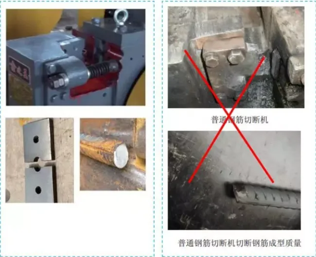
1.2 Reinforcement Straight Thread Processing
Basic requirements:
1. Use a grinding wheel cutting machine or a semi-circular blade steel bar cutting machine to ensure the ends of steel bars are straight, without horseshoe or offset.
2. The use of regular steel bar cutting machines is strictly prohibited.
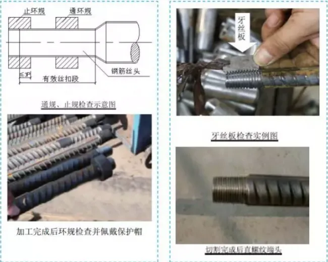
Additional requirements:
1. When inspecting the diameter of the steel wire thread, the through ring gauge must smoothly screw through the entire effective thread length. The depth of the stop ring gauge screwed into the wire head should be ≤ 3p (where p is the pitch).
2. The effective length of the threaded joint is tested using a dedicated wire head clamp, with an allowable deviation of ≤ 1p.
3. After threading, a protective cap must be installed to protect the thread.
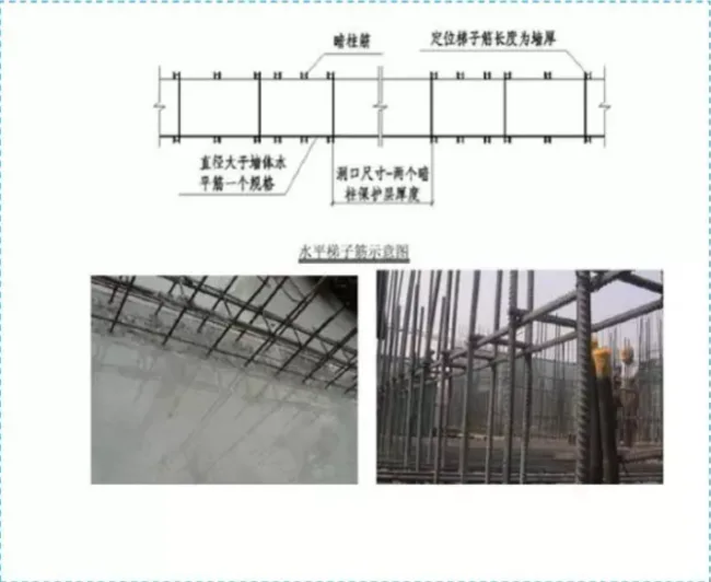
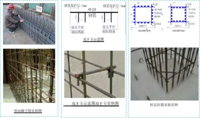
1.3 Wall Positioning Steel Bars and Column Positioning Hoops
Basic requirements:
1. Horizontal ladder reinforcement is fixed 150-200mm from the top of the wall to control the spacing and position of vertical reinforcement.
2. Vertical ladder reinforcement is fabricated by welding steel bars one size larger than the wall’s vertical steel bars and can replace them. Prefabricated assemblies are installed every 0.8 meters.
3. For wall reinforcement diameters greater than 16mm, vertical positioning reinforcement can be removed and replaced with double F-card positioning. The clip ends should be cut with a toothless saw and coated inward with 15mm anti-rust paint.
4. Column positioning clamps are set 500mm above the floor elevation, with center spacing equal to the steel bar diameter plus 3mm.
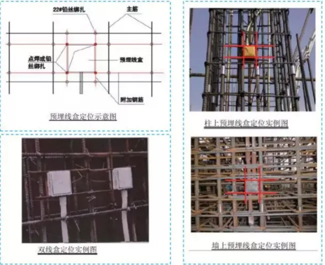
1.4 Pre-embedded Construction of Wire Box
Basic requirements:
1. To achieve one-time molding of pre-embedded wire boxes in walls, installation must occur after tying column and wall steel bars but before closing the mold. The wire box is fixed in place, then coated with film so that its outer surface is flush or slightly recessed (about 2mm) from the wall surface.
2. Two additional steel bars in both longitudinal and transverse directions are used for fixation, which can be spot welded.
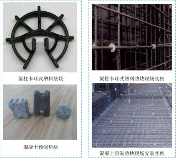
1.5 Prefabricated Cushion Blocks
Basic requirements:
1. Concrete precast cushion blocks are recommended for beam and slab bottom cushions; marble cushion blocks are prohibited.
2. Reinforcement protection layers on beam and wall sides can be controlled using double F-clamps and cushion blocks.
2. Formwork Engineering
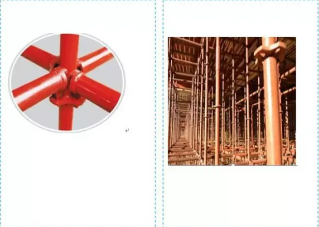
2.1 Wheel Buckle Scaffolding
Basic requirements:
This structure is simple, reasonable, easy to use, safe, and easy to store and maintain. The frame ensures proper spacing of uprights, placement of sweeping rods, step distance, and height of the top free end. It also facilitates easier removal of wall formwork without prematurely removing supporting rods, maintaining overall frame stability.
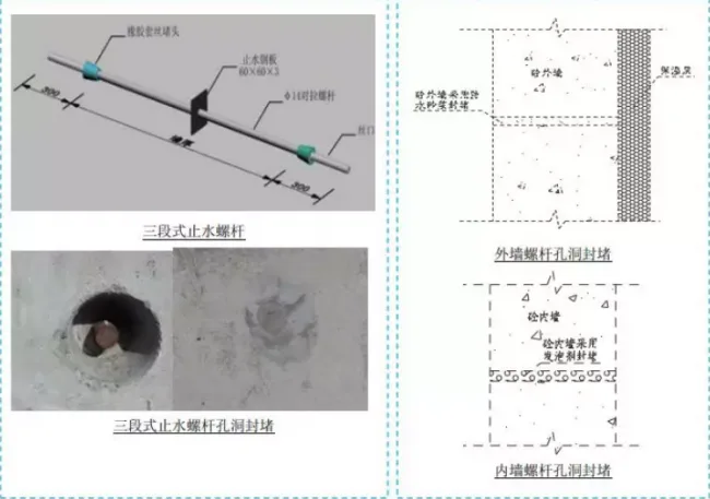
2.2 Pulling Screw
Basic requirements:
1. Basement exterior and civil air defense walls with functional requirements must use new three-stage waterproofing screws.
2. Waterproof screw holes in basements are sealed with waterproof mortar; inner wall sealing must be coated with anti-rust paint before whitewashing.
3. Ordinary exterior wall screw holes are sealed with 1:2 dry hard cement mortar (with waterproofing and expansion agents), while interior wall bolt holes are sealed with foaming agent.
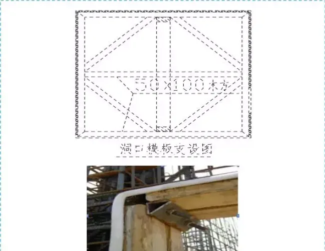
2.3 Installation of Portal Formwork
Basic requirements:
The entrance template is fabricated to standardized dimensions per drawings. Internal and external corners are reinforced with angle steel and wooden templates, supported by double-row bidirectional and diamond-shaped supports. The bottom has exhaust holes, and sponge strips prevent leakage along sides. Concrete is poured simultaneously from both sides of the entrance to prevent template displacement.
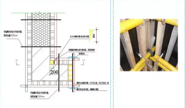
2.4 Yin Angle Control
Basic requirements:
Double-row steel pipes are staggered in length and locked with cross intersecting fasteners. Two wooden blocks are placed horizontally at the inner corner, reinforced by cross intersecting steel pipes. Staggered edges are aligned and gaps sealed tightly with wooden wedges. The first through-wall screw is placed 200mm from the edge.
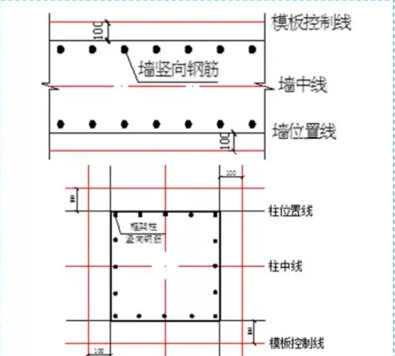
2.5 Wall Positioning Line
Basic requirements:
1. The positioning axis and cross-sectional dimensions of shear walls are marked with double lines: the shear wall edge line and a 100mm control line. For steel formwork, the control line can be 200mm.
2. For frame columns, double lines indicate the position line and a 100mm control line. For steel templates, the control line can be 200mm.
3. Concrete Engineering
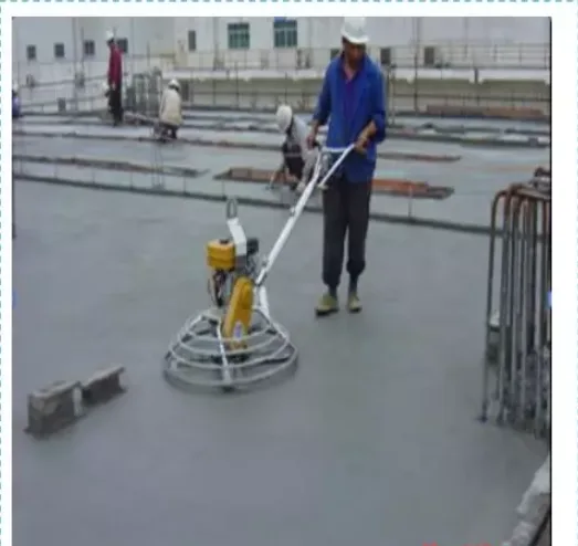
3.1 Concrete Pouring Elevation and Finishing Control
Basic requirements:
1. When pumping concrete, use effective controls to maintain floor height, such as infrared laser levels for real-time monitoring or standardized measuring molds.
2. Before concrete sets, promptly smooth and polish the surface. For large areas, use artificial iron trowels to close surface cracks.
3. Areas reserved for openings, pouring strips, and sinking plates require manual smoothing.
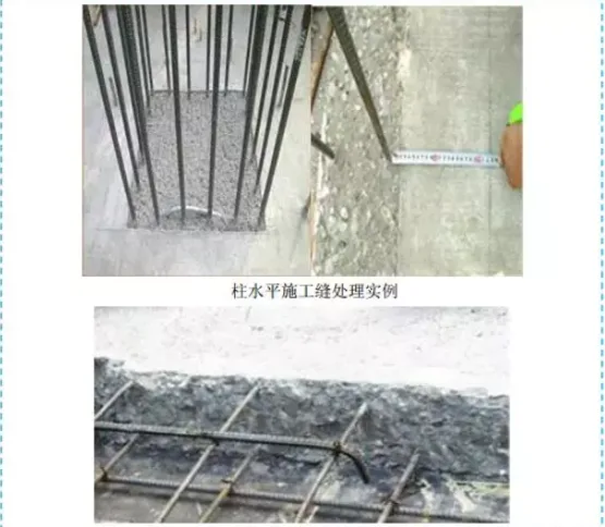
3.2 Construction Joint Treatment
Basic requirements:
1. For wall and column joints, once concrete strength reaches 1.2MPa, immediately remove surface slurry and weak layers, then chisel to create a 10mm concave surface ensuring joint quality. Fully moisten without water accumulation. During winter, use an air pump instead of water for cleaning.
2. For slab joints, remove loose stones and concrete, and clean thoroughly.
3. Before chiseling, mark the chiseling line to ensure straight edges.
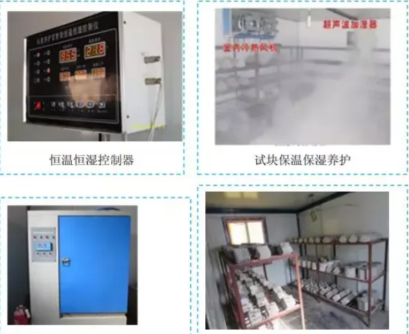
3.3 Standard Curing Room for Concrete Test Blocks
Basic requirements:
1. The laboratory must be managed by dedicated personnel.
2. The layout and specific methods are detailed in the “Detailed Drawing of Concrete Test Block Standard Curing Room” by China Construction Second Engineering Bureau Northeast Branch.
3. Equipment includes a constant humidity and temperature chamber (air conditioner, humidifier), thermometer, hygrometer, vibration table, slump cone, platform scale, test block molds, water tank, air pressure pump, racks, shovels, recording tools, and cleaning tools.
4. Temperature and humidity records must be kept at least twice daily. The concrete test block production room should maintain 15-25 ℃, with ideal curing conditions at 20 ± 2 ℃ and over 95% humidity.
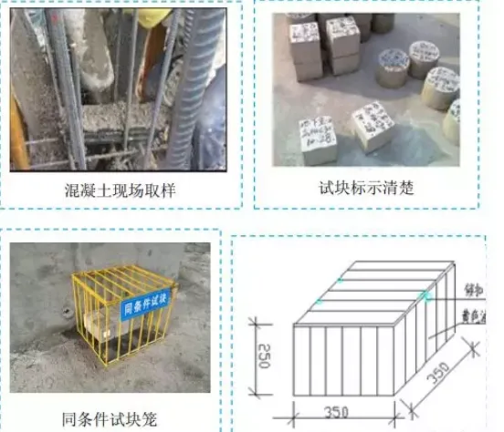
3.4 Production of Concrete Test Blocks
Basic requirements:
1. Dedicated personnel are responsible for producing concrete test blocks.
2. Samples must be taken at the concrete outlet for standard curing, not directly from the truck. Sampling should be under the same conditions at the working surface.
3. Each test block must be labeled with location, specimen number, molding date, and strength grade.
4. Test blocks should be placed near corresponding structural components, inside locked steel cages, with consistent curing methods.
5. Sample numbers must meet regulations and actual needs; during winter, add at least two extra groups.
6. Test block cages are welded with ¢6.5 or ¢8 steel bars, locked and sealed. Dimensions: 35cm x 35cm x 25cm, painted yellow, and labeled.
4. Masonry Works
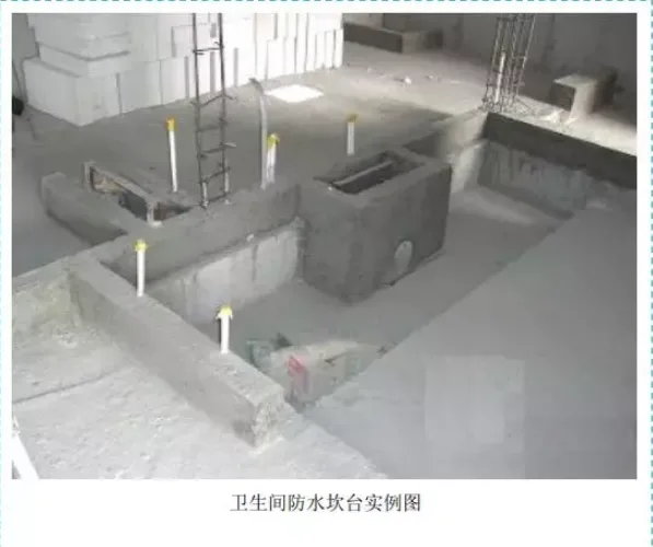
4.1 Toilet Waterproof Platform
Basic requirements:
1. When using lightweight aggregate concrete hollow blocks or autoclaved aerated concrete blocks for walls in kitchens and bathrooms, cast-in-place concrete platforms should be installed at the wall base. The platform height should be 150mm, and width reduced by 1-2cm according to wall design.
2. To prevent formwork displacement during guide wall construction, use wooden splints or fixtures made of wooden blocks and screws for fixed support. Step-by-step reinforcement is prohibited.
3. Use a small vibrator during pouring to compact and level the guide wall surface.
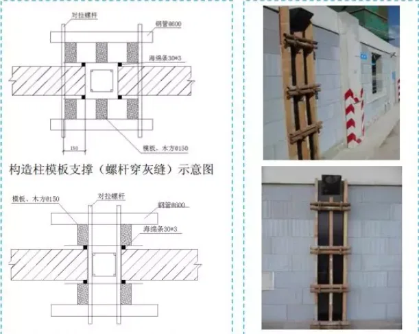
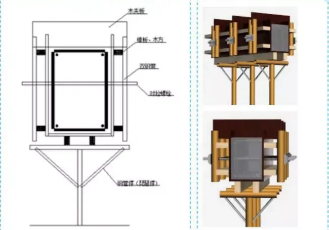
4.2 Prefabricated Construction Column Formwork
Basic requirements:
1. Use steel pipes for supporting column formwork, tied with through-wall bolts. Installing scaffolding eyes in walls is strictly prohibited.
2. When constructing column formwork, consider setting concrete pouring flares; chiseling the flare opening should be done after structural acceptance.
3. Apply sponge strips on both sides before formwork installation to prevent grout leakage.
4. Fix the template with tension bolts, two per row, spaced 500mm apart. Use new templates for setting and installation.
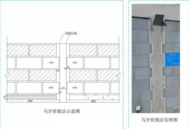
4.3 Ma Ya Cha Method
Basic requirements:
1. Structural columns on both sides of the infill wall should be built with horse tooth joints. The concave-convex size must be at least 60mm, and height must not exceed 300mm. Masonry should be symmetrical, stepping back first, then moving forward.
2. Size deviations in horse tooth joints should not exceed two per structural column.
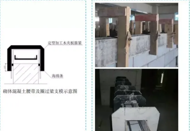
4.4 Construction Method of Masonry Concrete Belt and Ring Beam Formwork
Basic requirements:
1. When masonry concrete belts and rings pass through beam support formwork, use wooden splints or fixtures made from wooden blocks and screws to prevent displacement.
2. Apply sponge strips to edges before formwork installation to avoid grout leakage.
4.5 Method of Beam Formwork
Basic requirements:
1. When supporting masonry beam formwork, fixed wooden planks or fixtures made from wooden blocks and screws must be used to prevent displacement.
2. Apply sponge strips to edges before formwork installation to prevent grout leakage.
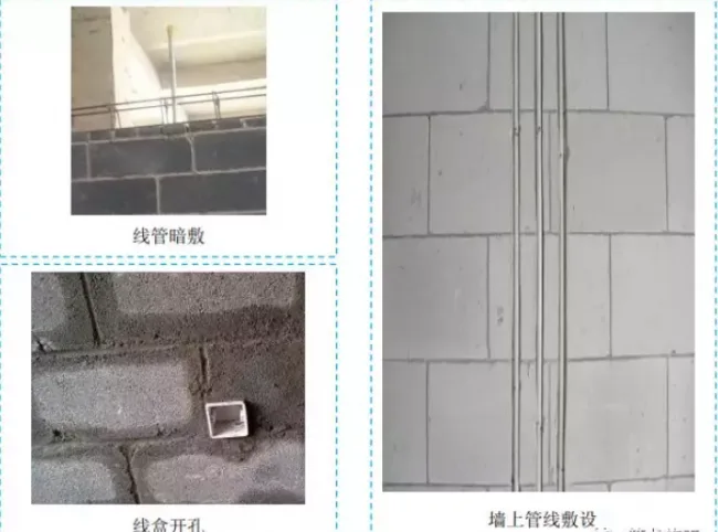
4.6 Machine Wire Conduit Slotting
Basic requirements:
1. Mark the conduit groove line straight and accurately to facilitate laying and reinforcement.
2. Use a reciprocating saw to cut along the marked line; violent slotting is prohibited.
3. Hollow block masonry conduits must be constructed using concealed application methods; wire box openings should not exceed 10cm.
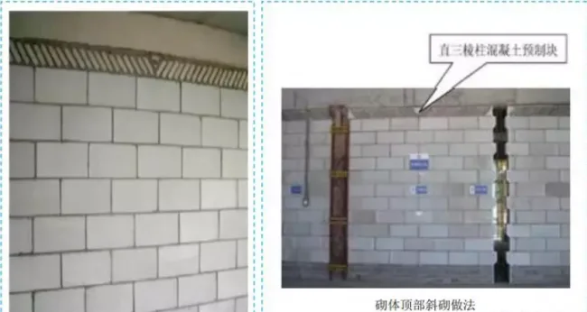
4.7 Diagonal Masonry of Masonry Top Blocks
Basic requirements:
1. The top of masonry walls should be constructed with small solid blocks set at a 30° to 60° inclination.
2. Walls should not be built to full height in one go to prevent settlement and gaps.
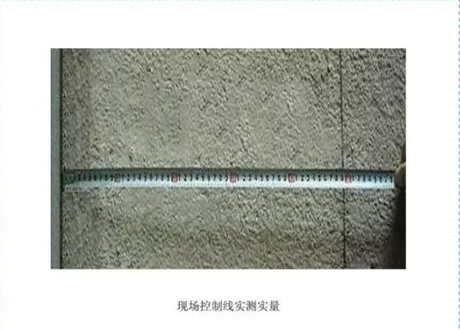
4.8 Secondary Structural Wall Experience Line and Brick Layout Diagram
Basic requirements:
1. After installing masonry wall lines, the project’s quality inspection department should conduct a proportional inspection and record the results to ensure accurate wall positioning.
2. Check interior and common areas (like stairwells) to confirm correct door and window opening elevations.
3. Before masonry begins, number secondary structural walls per drawings, provide corresponding brick layout diagrams, post them onsite, and keep workers informed.
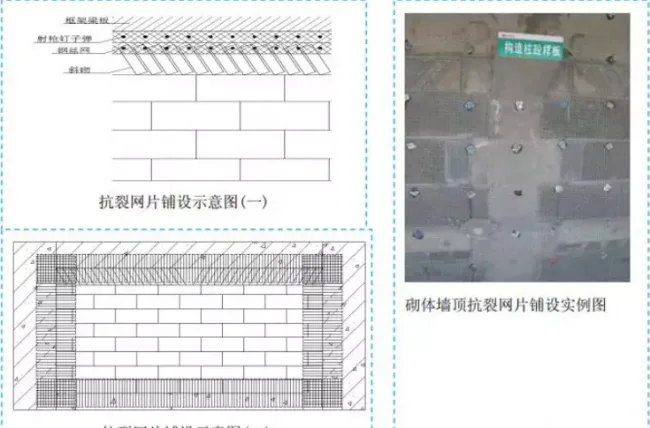
4.9 Basic Regulations for Laying Anti-Cracking Mesh
Basic requirements:
1. Reinforcement measures must be applied at the junctions between masonry walls and reinforced concrete to prevent cracking. Overlaps between anti-cracking mesh and structural components must meet specification requirements.
2. Hanging materials can include galvanized steel wire mesh, galvanized steel plate mesh, alkali-resistant fiber mesh cloth, and others.
3. The anti-cracking mesh must be firmly fixed with nails.
4. Overlaps between mesh sections must be at least 100mm. After fixing, the mesh should be flat, continuous, and firmly attached without deformation or arching.
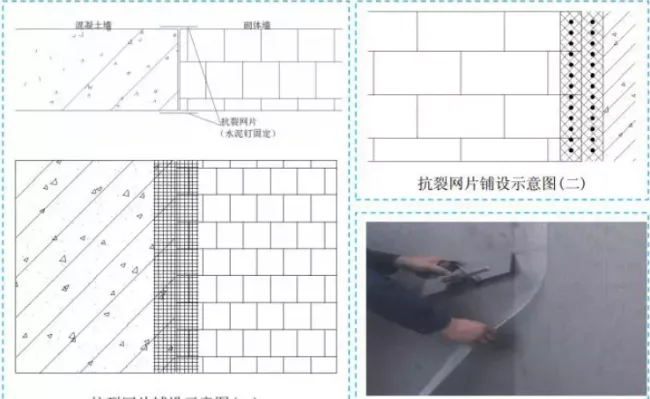
4.10 Masonry Wall and Wall Side Connection
Basic requirements:
1. The connection between the top of masonry walls and the bottom of beams, as well as between masonry walls and concrete columns, must be reinforced with anti-crack mesh. Overlaps on both sides should meet or exceed specification requirements, ideally 200-300mm.
2. Horizontal and vertical mesh overlaps must be at least 100mm.
3. Reinforcement mesh at aerated concrete block corners should be applied on both sides of the same plane with a minimum thickness of 200-300mm.
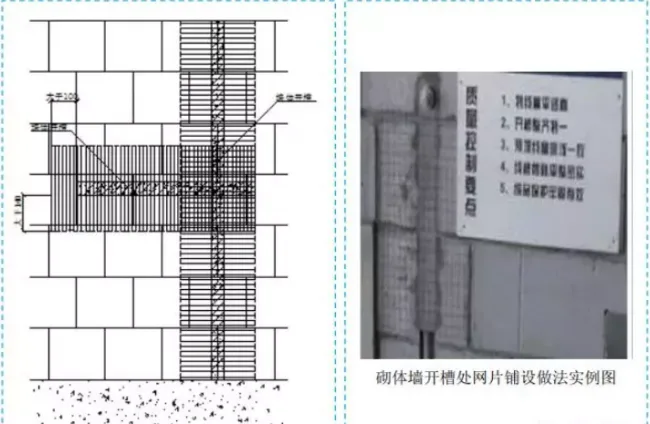
4.11 Laying Method of Mesh at Slotted Parts of Masonry Walls
Basic requirements:
1. Anti-cracking mesh should be buried at masonry wall slot locations, extending at least 100mm on each side.
2. Mesh must surround the groove for at least 100mm.
3. For horizontal and vertical slotting, anti-crack meshes must intersect with a minimum 100mm overlap. Horizontal and vertical meshes must be installed separately; the same mesh cannot serve both.
5. Special Projects
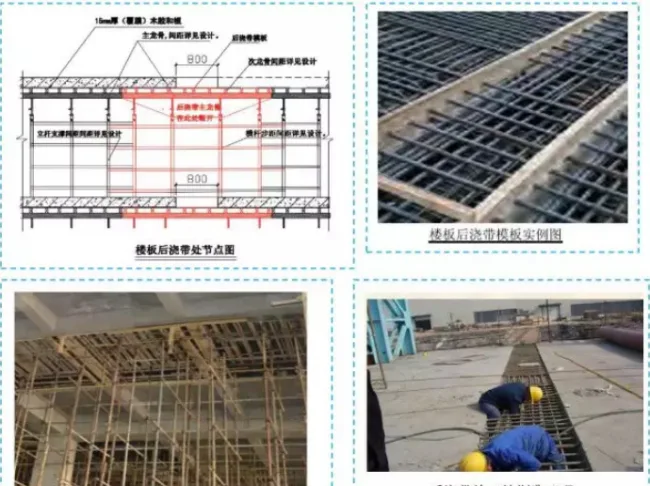
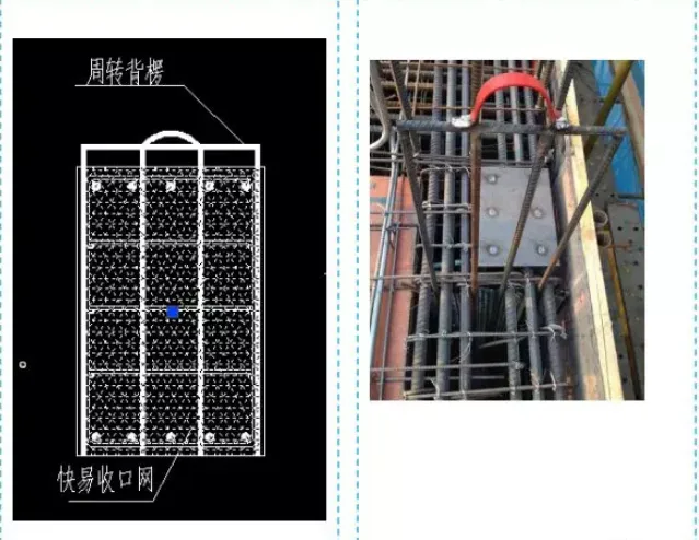
5.1 Post-Pouring Strip
Basic requirements:
1. The sealing of post-pouring strips uses steel wire mesh combined with wooden beams or quick-closing mesh.
2. Water stop steel plates must meet drawing specifications for material, thickness, and dimensions, with full welding. The groove must face upstream and be sealed.
3. Post-cast strip formwork uses an independent support system. To facilitate cleaning and material transport later, inclined supports should be added appropriately.
4. Clean the post-pouring strip before sealing and strictly follow construction drawings during concreting.
5.2 Control of Different Grades of Concrete for Beam-Column Joints
Basic requirements:
1. When beams and columns are made with different concrete grades, use quick-closing mesh placed at 90° angles combined with turnover back ribs. This stabilizes the mesh and controls concrete flow. Back ribs can be removed for reuse after concrete initial setting.
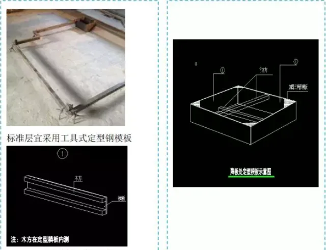
5.3 Sinking Plate
Basic requirements:
1. For sinking plate heights under 100mm, use a tool-type cornea fixed directly without additional support. Positioning must be accurate; wooden braces alone are prohibited.
2. For heights between 100-300mm, use mirror templates with formwork supported by back wooden beams, reinforced with cross braces or welded triangular brackets.
3. Heights over 300mm require separate calculation.
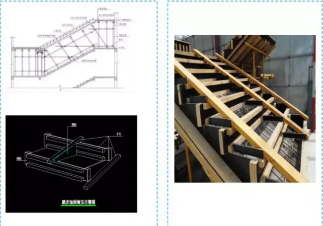
5.4 Key Points of Staircase Construction
Basic requirements:
1. Construction joints in staircases can be left at one-third of the platform slab.
2. Staircase formwork must be supported by inclined vertical double-row steel pipes; single wooden rake supports are strictly prohibited.
3. Stair step vertical boards must align with the step surface to avoid gaps caused by longitudinal wood joints.
4. Concrete finishing should begin immediately after pouring, with initial finishing after vibration and a second finishing before initial concrete setting to ensure quality.
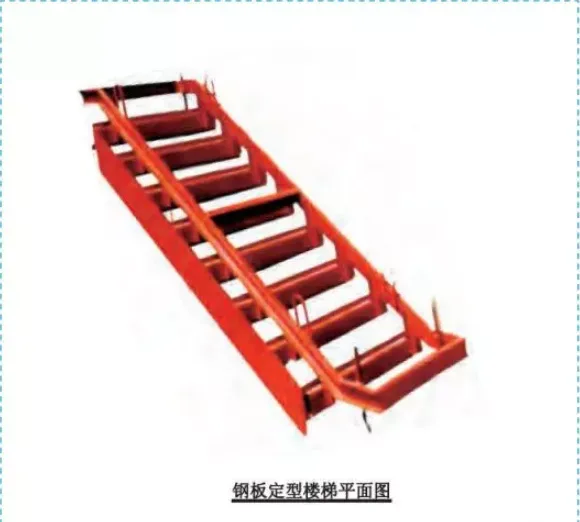
5.5 Standardized Steel Stairs
Basic requirements:
The standardized steel staircase template features excellent rigidity and can be assembled and disassembled as a whole, ensuring stair step quality and achieving a plain concrete finish.
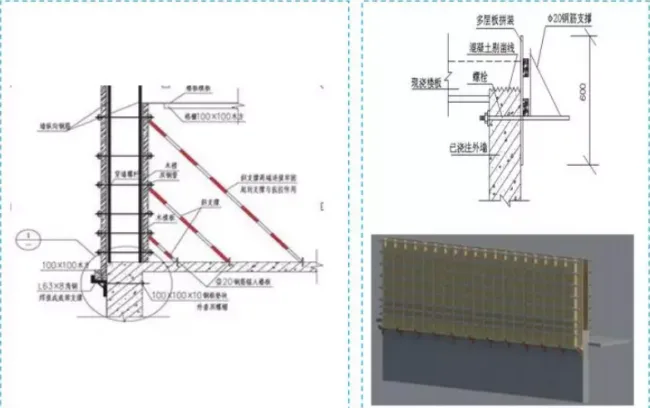
5.6 External Wall and Elevator Shaft Connection
Basic requirements:
1. To prevent formwork expansion at wall junctions, draw bolts are installed at 500mm intervals on the lower wall.
2. Before supporting upper formwork, apply a 30mm wide double-sided adhesive tape on the horizontal cut surface to enhance sealing between formwork and concrete, reducing slurry leakage and ensuring joint quality.
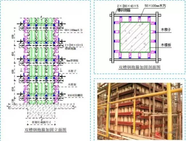
5.7 Framework Column Template Support
Basic requirements:
1. Double channel steel hoop reinforcement is suitable for frame columns with cross-sectional dimensions ≥ 1200mm, providing sufficient rigidity and stability to withstand concrete weight, lateral pressure, and construction loads.
2. The length of channel steel should be determined based on the frame column’s cross-sectional dimensions.
3. Double channel steel is fabricated by welding two single channel steels together.
4. These design parameters are for reference; actual construction should be calculated per design requirements.
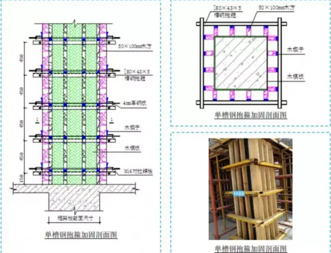
Additional requirements:
1. Single channel steel hoop reinforcement is suitable for frame columns with section size < 1200mm, providing sufficient rigidity and stability to withstand concrete weight, lateral pressure, and construction loads.
2. Channel steel length should be based on cross-sectional dimensions.
3. Bolt hole positions and sizes should be determined based on actual site conditions.
4. The above parameters are for reference only; construction should follow design calculations.


Must log in before commenting!
Sign Up