Construction engineering is a systematic process. To ensure project quality and deliver outstanding results, it is essential to control not only the technical aspects but also the construction site and overall management.
Construction Measures Control
01. Fully Cast-In-Place Exterior Wall
Basic Elements
(1) Foundation Pit Axis Positioning: Confirm the accuracy of the BIM training pile position used for axis control. Position the control pile carefully and protect control points within the foundation area. Conduct dimensional verification.
(2) Foundation Trench Axis Positioning: Verify the location of the axis control pile and measure the primary axis relative to the cushion layer. Perform closed calibration and detailed axis line measurements. Complete a line inspection after finishing.
(3) Elevation Control: Jointly measure elevation control network points to confirm the accuracy of benchmark points. After completion, measure elevations precisely. Each floor must have at least three reference elevation points on the same plane, which should be cross-checked for accuracy.
Main Components
(1) On the first floor plane, recheck and verify the main control axis and subdivide secondary control points. A 200mm × 200mm prefabricated structure hole is reserved at the same spot on each floor’s structural slab to transfer the axis upward sequentially. After projection, verify distances again, ensuring control accuracy within 2mm.
(2) Floor Elevation Transfer: During construction of the main upper structure, use a steel ruler to measure vertical height directly. Transfer elevation upward via relay, maintaining the steel ruler’s verticality. The error per floor should not exceed 3mm, with a total floor error under 15mm.
(3) Floor Layout: Based on control axis positions, verify wall and column reinforcement locations, and set a 300mm control line around the formwork. After removing the formwork, extend this line to the wall to determine the position of the upper beam.
Decorative Components
(1) For indoor decorative surfaces, plane control should rely on the structural construction control line, while elevation control should be based on the building’s 50 elevation line. Ensure intersection closure with errors within allowable limits.
(2) The four corners of the exterior wall must be aligned with control lines, ensuring verticality, squareness, and proper vertical projection connections.
02. Key Quality Control Points
Building Materials and Equipment Quality
At the start of material and equipment procurement, engineering and technical staff should specify quality requirements based on design drawings and standards, clearly outlined in the procurement contract. All materials and equipment delivered to the site must be inspected and tested according to relevant regulations to ensure quality.
Quality of Finished and Semi-Finished Products
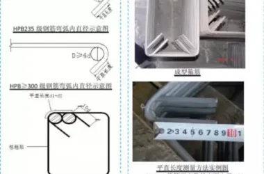
Some materials require secondary processing. Controlling the quality of finished and semi-finished products is vital for overall project quality. For steel reinforcement, after passing inspections, steel bars must be straightened, cut, shaped, stacked, and lifted. Processing dimensions of vertical and horizontal bars for walls, beams, columns, and slabs must be accurate, and deformation prevention measures should be taken during stacking and lifting.
Mold Quality
Molds refer to templates and tools used to shape concrete. The selection, sizing, and durability of molds directly impact concrete quality. Control geometric dimensions, stiffness, deformation, and trimming during mold fabrication.
Reinforced Steel
1. Wall Reinforcement Binding
(1) Verify that steel bars and concrete surfaces are thoroughly cleaned of contaminants; (2) Ensure floating slurry inside walls is removed and chiseled properly, exposing stones; (3) Confirm steel bars on ground walls extend at least 50cm in height; (4) Check that steel bars in hidden columns are staggered with a minimum height difference of 35cm; (5) Adjust offset steel bars at a 1:6 ratio after layout; (6) Ensure hidden column reinforcement ends are horizontal and smoothed; (7) Confirm presence of 5cm wall reinforcement on each side of hidden columns.
2. Electric Slag Pressure Welding of Column Steel Bars
(1) Welding flux must be dry; (2) Clamp rings should be qualified and secure; (3) Welding flux must be evenly compacted; (4) Welding packages must be uniform without visible burns on steel surfaces; (5) Joints must be concentric vertically, with deviation no greater than 0.1% of steel bar diameter (d) and less than 2mm; (6) Joint bending angle should not exceed 4°.
3. Concealed Column Hoop Reinforcement
(1) Vertical reinforcement must be perpendicular to hoop reinforcement; (2) Hoop hooks must meet a 135° bend requirement; (3) Hoop reinforcement straight lengths should be 10d and run parallel; (4) Check for any loose or missing buckles; (5) Place hoop reinforcement 5cm from the ground; (6) Confirm verticality of hidden column reinforcement.
4. Beam Reinforcement and Hoop Binding
Beam hoop reinforcement must be perpendicular to upper and lower beam bars. Ensure hoop reinforcement is placed 5cm from both sides of hidden columns. Verify no missing or loose fasteners.
5. Wall Reinforcement Binding
(1) Confirm one wall reinforcement on each side, 5cm from hidden column edges; (2) Ensure at least three horizontal bars in overlapping vertical bar sections; (3) Include at least three buckles in overlapping steel bar sections; (4) Maintain horizontal bars horizontally and vertical bars vertically; (5) Ladder bar spacing should not exceed 2m, with anti-rust coating on upper, middle, and lower parts; (6) Hook spacing must be under 80cm, arranged in a plum blossom pattern; (7) Plastic pad spacing should not exceed 80cm, also in a plum blossom pattern; (8) Tie wall reinforcement point by point, with no loose or missing buckles; (9) Ensure all fastening threads face inward and are pushed opposite for binding; (10) Keep work surface clean of debris.
Smart Construction Technologies
1. All-Steel Intelligent Climbing Frame
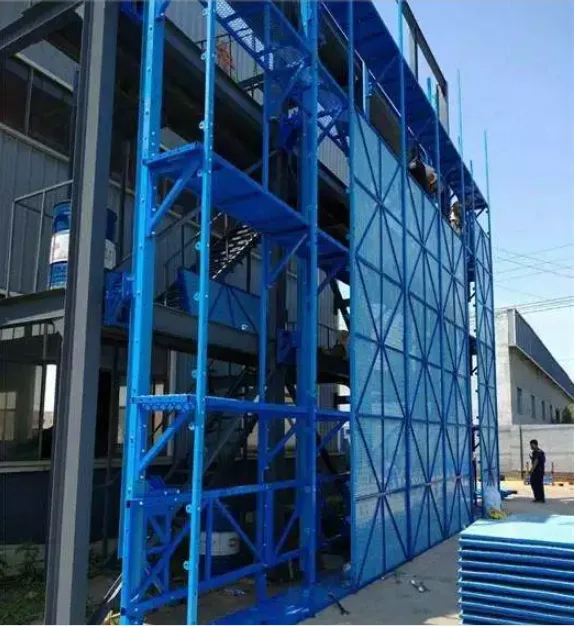
This system offers advantages such as enhanced safety, energy efficiency, and environmental protection. The climbing frame progresses alongside the main building and can be dismantled just two weeks after main construction completion, facilitating overlapping construction activities.
2. Aluminum Alloy Formwork
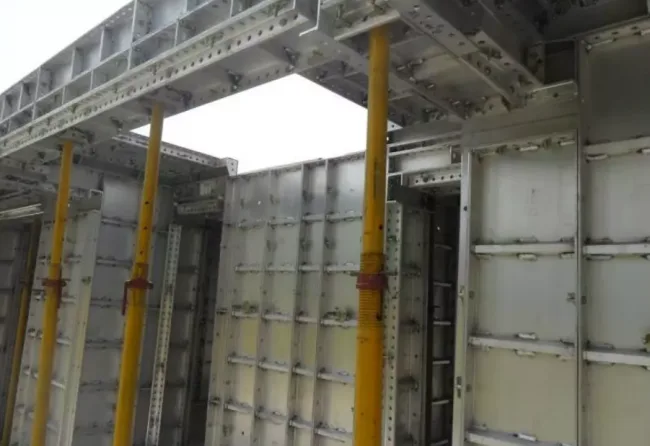
Aluminum alloy formwork boasts high stability, environmental friendliness, efficiency, strong load-bearing capacity, and excellent construction quality. Its rigidity and durability allow multiple uses, improving concrete construction accuracy from centimeter to millimeter levels. This eliminates the need for plastering and prevents quality issues like hollowing.
3. Floor Water Interception System
This system manages water and rainwater interception and drainage during floor construction, enabling dry and wet zoning. It supports concurrent decoration and construction processes.
4. Precast Concrete (PC) Staircase
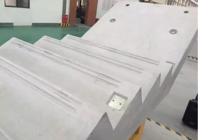
Designed and manufactured with strict dimensional control, PC staircases simplify installation and quality oversight. This approach shortens construction cycles and allows factory production, promoting energy saving and environmental protection.
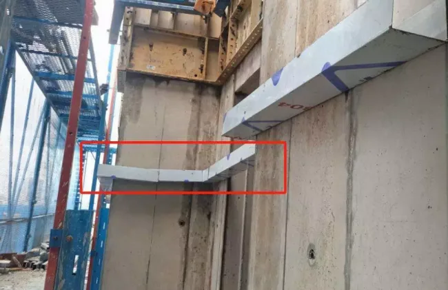
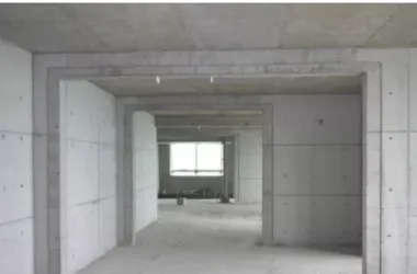
5. Fully Cast-In-Place Exterior Wall
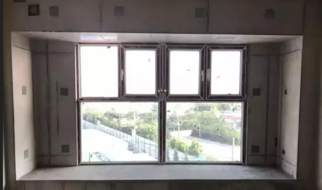
During design, aluminum molds and structural seam drawing techniques optimize exterior door and window openings, waterproof joints, and more. The main structure is poured continuously, eliminating the need for secondary external wall structures and plastering. This achieves structural self-waterproofing and reduces quality hazards like leaks around walls and windows.
High-Quality Practices in Quality Management
The construction quality model demonstration area showcases project standards through building entities and movable models.
On-site, a civil engineering processing area is established for block cutting and prefabrication of irregular components.
A water and electricity processing workshop produces pipeline box accessories and assembles prefabricated supports and hangers to streamline installation.
Pipeline installation and layout in wells are uniform; instrument installations maintain consistent height and direction; pipeline insulation is complete and aesthetically pleasing. Floor slab penetrations are sealed per regulations; pipelines and embedded sleeves are concentric and coaxial.
Structural embedded pipes and box positioning are planned and executed comprehensively.
In the distribution room, cable trenches use angle steel frames for cover plates and trench edges. Cover plate sizes are precisely controlled, edges are straight, and the ground surface is flat with minimal gaps.
Roof equipment and pipeline terminations are neatly arranged. Ground separation and equipment zoning are consistent, presenting a clean and bright appearance.
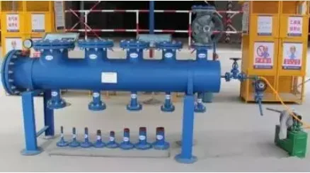
On-site, combined valve testing devices standardize testing for various valve specifications.
Electrical pipeline box installation templates visually demonstrate correct and incorrect methods, effectively guiding on-site construction.
Prefabricated pipeline support technology offers advantages over traditional supports, including easy assembly, improved installation efficiency, shorter construction periods, elimination of welding and painting, enhanced corrosion resistance, reduced maintenance costs, attractive finishes, easy system modification, and recyclable materials.
For sealing cable trays passing through floor slabs: floors are tiled, ceilings use aluminum-plastic panels or decorative lines, and gaps between trays and structures are sealed with fireproof adhesive. Fireproof filling materials are standardized and visually pleasing.
Cable trays are connected by joint sections to prevent leakage and bending deformation, improve joint strength, and present an overall attractive appearance.
Secondary structural sample displays include pre-construction planning for brick layouts, correct cutting angles for inclined bricks on wall tops, efficient use of triangular cement bricks, firm support of structural column formwork, and tight sealing of formwork gaps.
Standardized plastic products are used for stair skirting and drip lines, offering low material costs and smooth, visually appealing finishes.
Cover plates for water accumulation pits meet rigidity and load-bearing requirements, maintaining a flat, deformation-free appearance. Drainage system pipeline layouts and water accumulation pits are well-planned, with consistent instrument installation heights and directions.
After structure completion and waterproof layer installation, roof water storage tests ensure no leakage occurs.
On-site quality acceptance records document core control points, effectively managing quality throughout the construction process.
Enclosed brick masonry techniques ensure wall pipes are embedded without slotting, reducing waste and avoiding plaster cracking risks.
Cable trays, air ducts, pipe penetrations, and floor seals utilize customized plastic rings, aluminum-plastic panels, and stainless steel materials.
Roof decorative details are refined: drainage ditches are paved with dark tiles or marble; pipe penetration bases are finished with granite; exterior decoration of roof equipment bases includes granite and tile materials. Tile color matching is carefully planned, with zoning and arrangement avoiding half bricks.
Safety Facility Management
Active mobile platform supports improve platform safety during use.
Tower crane and high-altitude lighting cables are arranged using prefabricated fixed brackets, ensuring safe and aesthetically pleasing cable layouts.
Elevator shaft door protective facilities feature a flip-up design, providing safety while allowing easy access for construction personnel.
A combined protection system using half clips and tool-type supports is easy to disassemble and visually attractive.
Installation platforms and access channels for tower crane attachments are constructed in a tool style, ensuring safety and aesthetics.
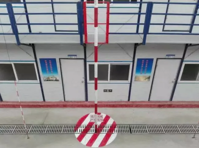
Escape poles and movable railings are installed in dormitory areas.
External protective scaffolding uses all-steel frames, which are visually appealing and eliminate fire hazards associated with traditional frames.
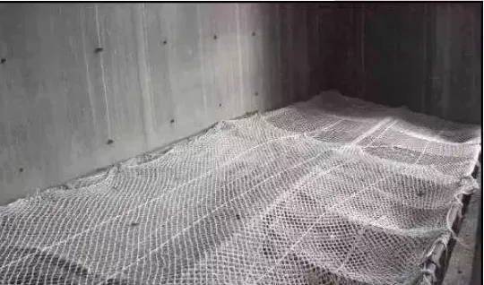
Elevator shaft soft and hard protections employ Ø8 round steel mesh with 200mm × 200mm spacing. This structure is pre-embedded during construction, with protective steel mesh removed before elevator installation for reuse. Tool-type horizontal soft protection may be applied in certain projects.
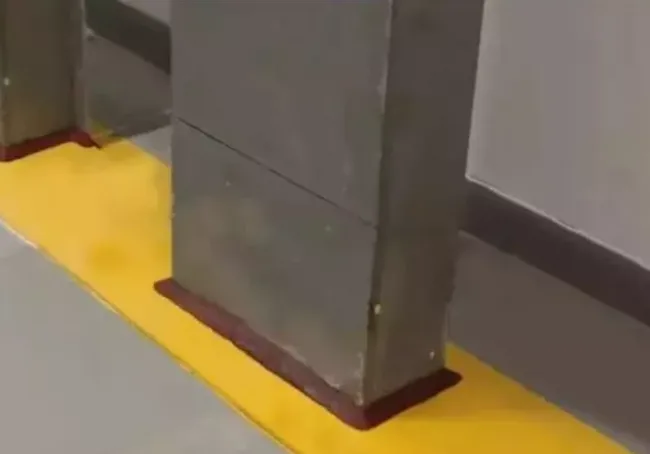
Tool-type movable isolation facilities are employed on-site to separate safe passages and material storage areas effectively, enabling flexible site zoning and maintaining a neat, attractive environment.
Article source: Architectural Technology Magazine


Must log in before commenting!
Sign Up