Key Design Considerations for Processing Detailed Drawings of Prefabricated Shear Wall Structural Components
Qi Bolei, Liu Yi, Yu Huan, Zhao Hengyu
Beijing Yantong Building Components Co., Ltd. 102200
Abstract: This article examines the design requirements and critical considerations for horizontal and vertical components within the assembled integral shear wall structural system. It covers prefabricated component design, production, and construction stages, clarifying key tasks at each phase and providing guidance for detailed design of prefabricated component processing drawings.
Keywords: professional collaboration; prefabricated composite panels; prefabricated shear walls; design points; EPC
Overview of Prefabricated Concrete Structures
Prefabricated concrete structures primarily consist of prefabricated components that are assembled and connected on-site. Compared to traditional cast-in-place methods, prefabrication supports green construction and aligns better with goals of land conservation, energy efficiency, material savings, water conservation, and environmental protection.
Currently, the design of prefabricated concrete structures typically follows the “equivalent cast-in-place” concept. Cast-in-place nodes and grouting sleeves serve as primary connection methods, ensuring the structure maintains the same integrity, stability, and ductility as cast-in-place forms. Structural types include assembled integral shear wall structures, assembled integral frame structures, combined frame cast-in-place shear wall structures, and multi-layer dry connection structures. This article focuses on the assembled integral shear wall structural system.
Collaboration Among Disciplines During the Design Phase
Using construction drawings, detailed mechanical and electrical engineering drawings, and fine decoration plans, detailed designs are developed for reserved and embedded parts, as well as pipeline slotting. This results in a comprehensive embedded parts layout, including:
- Architectural Reserves: Reserved openings for air-conditioning refrigerant and condensate pipes, panel floor drains, rainwater pipes, gas exhaust pipes, kitchen exhaust ducts, smoke ducts, and gas lines.
- Architectural Embedded Parts: Window railings, air conditioning railings and louvers, door and window installations, decorative moldings, and other embedded elements.
- Mechanical and Electrical Reserves: Lighting fixtures, switches, sockets, equipotential bonding, smoke detectors, infrared curtains, and embedded parts for lightning protection on doors, windows, and railings.
- Water Supply and Drainage: Kitchen drainage risers, bathroom drainage and ventilation risers, floor drains, toilet and washbasin drainage pipes, solar water supply and return pipes, reclaimed water modules, and reserved slots for water supply pipes.
Collaboration During the Construction Organization Stage
3.1 Construction External Frame Scheme: Define the relationship between the external construction frame and prefabricated components, and finalize detailed node drawings.
3.2 Tower Crane Model Selection: Choose a tower crane model balancing installation efficiency and cost-effectiveness.
3.3 Tower Crane Attachment Scheme: Avoid direct attachment of tower cranes to prefabricated exterior wall panels; instead, fix them to cast-in-place interior walls or floor slabs.
3.4 Cast-in-Place Section Formwork Scheme: Determine formwork fixation methods and develop detailed node diagrams.
3.5 External Elevator Attachment Plan: Establish reserved locations and node connection methods for elevator attachments.
The conversion layer, where cast-in-place components transition into prefabricated components, requires precise positioning of longitudinal bars to connect cast-in-place longitudinal bars with prefabricated sleeves. Reinforcement diagrams should specify:
- Positions and specifications of longitudinal steel bars at prefabricated component joints.
- Anchorage lengths of reinforcing bars in cast-in-place layers.
- Outward extension lengths of reinforcing bars.
4. General Requirements for Prefabricated Component Design
- The concrete strength grade must be at least C30, and durability must comply with GB50010-2010 “Code for Design of Concrete”.
- Design should minimize component variety and standardize steel bars and embedded parts to optimize mold usage.
- Prefabricated component methods should be optimized considering construction, installation, and production.
- Component size selection must account for production molds, transportation, and installation, favoring large panel formats where possible.
5. Design Principles for Prefabricated Components
Design must prioritize structural safety and comply with design specifications. It should consider production of individual components, coordination with adjacent components and cast-in-place parts, construction measures, reserved decoration, and stacking and storage logistics. Key principles include:
- Determining component arrangement and connection methods based on structural schemes and load paths, followed by comprehensive structural analysis and connection design.
- Ensuring components meet functional building requirements and standardized design criteria.
- Locating component connections in low-stress, easily constructed areas; connections must effectively transmit internal forces.
- Verifying all components and connections against potential adverse conditions during production, construction, and use.
- Using flexible connections between non-load-bearing components and the main structure.
- Coordinating design with the entire production and construction process to facilitate efficiency and cost reduction.
6. Key Points of Laminated Panel Design
6.1 Basic Requirements for Composite Panel Design
- Prefabricated parts of composite panels must be at least 60mm thick, with the post-poured concrete layer also no less than 60mm.
- Steel bar connections at panel supports and joints must comply with GB/T51231-2016 and JGJ1-2014 standards.
- Longitudinal load-bearing steel bars anchored into post-poured concrete supports must extend at least 5 times the bar diameter (5d) beyond the slab end and cross the support centerline.
- Where steel bars at side supports do not extend into supports, add steel bars in the post-poured concrete composite layer with cross-sectional area and spacing requirements.
- Joint surfaces between prefabricated panel ends and post-poured concrete should be roughened with a concavo-convex texture of at least 4mm depth, covering at least 80% of the joint area.
- Load-bearing plate ends placed on supports must extend at least 10mm.
- Roofs and floors with complex stress patterns should use cast-in-place slabs; composite panels in these cases require post-poured concrete thickness of at least 100mm.
6.2 Joint Design of Laminated Panels
Prefabricated housing panels use unidirectional plywood with a reserved post-pouring strip between panels, 60-200mm wide. Double-sided composite panel joints should align with secondary stress directions and avoid maximum bending moment sections. Joints are formed as post-pouring strips where load-bearing steel bars at the bottom overlap. Overlap lengths depend on whether bars are straight or bent at 135° or 90°, as illustrated below.
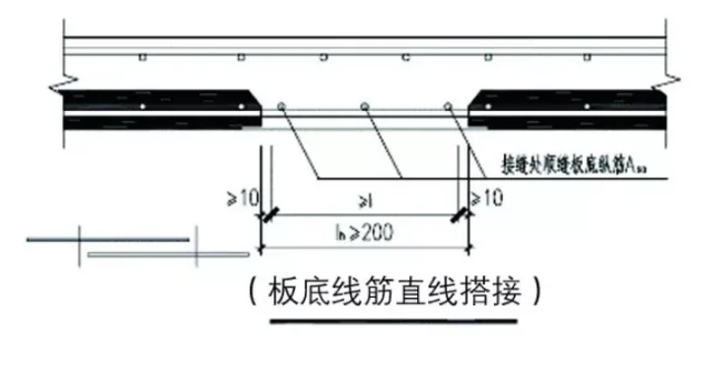
Figure 1: Joint Form of Post-Pouring Strip (I)
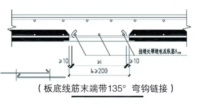
Figure 2: Joint Form of Post-Pouring Strip (II)
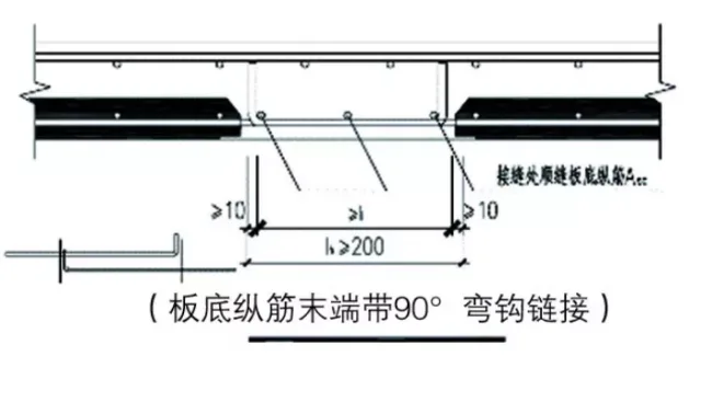
Figure 3: Joint Form of Post-Pouring Strip (III)
6.3 Layout of Truss Reinforcement Steel Bars
- Truss steel bars in prefabricated residential panels should align with main stress directions during demolding and hoisting.
- Distance from truss steel bars to slab edges should not exceed 300mm; spacing between bars should be 600mm or 700mm maximum.
- Lower chord reinforcement may align with slab bottom reinforcement; upper chord reinforcement should be selected based on slab length, preferably HRB400 steel; web reinforcement may use HPB300 or CRB550 steel bars, at least 4mm diameter.
- If lower chord reinforcement serves as load-bearing slab reinforcement, diameter must be at least 8mm; otherwise, no less than 6mm.
- Truss reinforcement length should be in 50mm increments.
- Arrange truss steel bars one layer above slab bottom bars.
- Avoid truss bars at openings; if unavoidable, cut after installation and pouring.
- Height of truss bars must accommodate conduit layout and protective cover requirements for upper slab reinforcement.
6.4 Mechanical, Electrical, and Construction Reserves
- Drainage pipes require reserved openings for kitchen drainage, gas pipes, bathroom floor drains, toilets, washbasins, ventilation, rainwater risers, etc. Reserved hole diameters should be 30mm larger than pipe outer diameters or match casing size.
- Water supply riser openings must consider insulation thickness.
- For reclaimed water modules in bathrooms, reserve holes on prefabricated boards with structural steel bars.
- Smoke and air duct openings should follow architectural requirements, generally expanded 50mm on wall sides.
- Electrical reserves include wire boxes and connectors as per design specifications. Reserve holes for switches, conduit wiring, and sockets; typically 30mm diameter for PC20 conduits.
- Reserve wire boxes or through holes for fire protection infrared curtains and smoke detectors installed on ceilings.
- Construction needs reserved holes for measuring, fabric poles, unloading platforms, ideally through holes not exceeding 140mm diameter.
- Cantilever holes on laminated panels are generally discouraged.
- If cast-in-place concrete strength is insufficient to support prefabricated walls, embed support components or reserve through holes on panels.
6.5 Layout of Demolding and Lifting Points for Composite Panels
- Suspension points can be designed at intersections of upper chord and web bars of trusses, reinforced locally with two steel bars at least 8mm in diameter.
- Lifting point placement should account for demolding suction forces and be determined by calculation; limit to four sets.
- Place wooden blocks near lifting points during component storage.
6.6 Layout and Numbering Principles of Laminated Panels
- After determining board joint forms and sizes, arrange composite boards along the depth direction; extended steel bar widths should not exceed 3m. Larger plates are preferred.
- Number composite panels according to external dimensions, reinforcement details, and embedded information to reflect mold universality and adaptability.
7. Design Points for Prefabricated Balcony and Air Conditioning Panels
7.1 Basic Design Requirements
- Balcony panels should be laminated or fully prefabricated; air conditioning panels must be fully prefabricated.
- For air conditioning panels with upper and lower flanges, forming in one step is recommended.
- Use prefabricated external panels or railings for balcony maintenance structures.
- Employ bridge-type embedded parts to connect prefabricated air conditioning panels to the main structure, eliminating the need for insulation during construction.
- Connection surfaces with the main structure should be roughened with concavo-convex textures at least 4mm deep, covering no less than 80% of the joint area.
7.2 Connection Nodes Between Balcony, Air Conditioning Panels, and Main Structure
- Connections must be reliable per Atlas G310-1~2 standards. Negative bending moment steel bars should anchor into adjacent post-poured concrete with an anchorage length not less than 1.1 times the anchorage length (1.1La).
- Bottom steel bars should extend at least 12 times the bar diameter (12d) into supports, passing through the support center.
- Check protruding steel bars for collisions with longitudinal bars of connecting beams and edge components.
7.3 Reserved and Embedded Layout
Reserve electrical junction boxes, condensate risers, floor drains, and rainwater pipes following laminated panel principles. Reserve railings and louver embedded parts as required.
8. Design Points for Prefabricated Stairs
8.1 Basic Design Requirements
- Stairs and fire-resistant partitions should be prefabricated.
- Prefabricated stairs should have fixed hinges on one end and sliding hinges on the other, allowing rotational and sliding deformation to accommodate interlayer structural movements. The minimum length of the stair end on supporting components should be at least 100mm.
- Fireproof partitions in scissor stairs should be prefabricated concrete at least 120mm thick, preferably connected with landings.
- Reserve a 20mm installation gap between stairs and walls, filled with pressure grouting.
- Upon reaching building surface layers, stairs should have rounded internal and external corners with anti-slip steps.
8.2 Staircase Connection Nodes
- Use simply supported connections between stairs and supports that meet deformation requirements under rare earthquakes.
- Sliding hinge ends must include measures to prevent slipping.
- A gap of at least 30mm should be maintained between sliding ends and supports, without filling rigid materials.
- Fixed hinges can be point or line connections, designed to meet stress demands.
8.3 Reserved and Embedded Layout
Reserve holes for stair railings to prevent surface damage during later construction. Use formwork technology for stair production, and pre-embedded hanging nails for demolding and lifting.
9. Design Points for Prefabricated Shear Walls
9.1 Basic Design Requirements
- Component weight should be balanced to control lifting costs, generally between 5-8 tons.
- Outer blade thickness must be at least 60mm with a minimum concrete strength of C30. Outer blade steel mesh should use steel bars at least 4mm in diameter, preferably CRB550.
- Outer blade surfaces may feature finishes such as plain concrete, ceramic tiles, stone, texture, or paint.
- Grooves for lines or shapes on outer blades should not exceed 20mm depth, preserving steel mesh protective layer thickness.
- Under-window infill walls use polystyrene boards of at least 12kg/m³ density, encased in double-layer bidirectional steel mesh (8mm diameter, 200mm spacing), with rounded filler edges and a 100mm diameter concrete pouring hole. Maintain a 50mm minimum distance from fillers to walls or beams.
9.2 Layout of Prefabricated Shear Wall Components
- Bottom reinforcement zones of shear walls should be cast-in-place concrete. For seismic grades 2 or 3 and axial compression ratios ≤ 0.3, partial assembly is permitted.
- Corners should be L- or U-shaped components; other positions may use straight, I-shaped, or knife-handle-shaped components.
- To avoid mixed cast-in-place and prefabricated external frames, it is recommended to assemble all exterior walls for a closed outer panel system and unified facade construction.
- Outer blade extension beyond inner blade should not exceed 900mm.
9.3 Construction Requirements for Prefabricated Shear Wall Components
- Interfaces between prefabricated shear walls and cast-in-place concrete must be roughened with an average depth of at least 6mm.
- Reinforced concrete protective layers must be at least 15mm thick on horizontally and vertically distributed steel bars, connecting beams, and edge stirrups, with minimum 25mm net spacing between steel bar sleeves, complying with GB50010-2010.
- Protective layers on the outer side of prefabricated sandwich insulation exterior wall panels must be at least 20mm thick.
- Install crack-resistant steel bars at stress concentration points like door and window corners.
- Use welded closed hoops or closed hoops with 135° hooks for reinforcement.
- Longitudinal steel bars of edge components must be vertically connected without bending, avoiding main load-bearing bars when embedding connectors.
- Steel reinforcement grouting sleeves may be full or half grouted; anchorage length in sleeves must be at least 8 times the bar diameter (8d), with cutting lengths controlled based on positive deviation.
- Within 300mm from sleeve bottoms to tops and upward, horizontal distribution and hoop reinforcement must be densified: 100mm spacing for seismic levels 1 and 2, 150mm for levels 2 and 3, using steel bars at least 8mm in diameter. The top steel bar should be within 50mm of the sleeve top.
- Longitudinal steel bars of connecting beams should be outside edge component bars, with 55mm spacing between sleeve steel bars and wall edges along thickness.
- Vertical distribution steel bars of upper and lower prefabricated shear walls should be double-row connected. Single-row connections must meet “Technical Standards for Prefabricated Concrete Buildings.” Double-row plum blossom connections require reinforcement ratios meeting GB50011-2010 seismic design standards. Connecting bar diameters should be at least 12mm, with spacing not exceeding 600mm.
- Vertical connecting steel bars for seismic grades I and II should be at least 1.2 and 1.1 times the actual vertical steel bar area in the wall, respectively.
- If horizontal joint shear capacity at the shear wall base is insufficient per DB11/1003-2013, shear steel bars or embedded parts should be added.
- For doors and windows on insulation layers, use anti-corrosion wooden bricks; for inner blade installation, reserve expansion nuts.
9.4 Connection Nodes of Prefabricated Shear Wall Components
- Horizontal steel bars connecting overhanging bars on both sides of prefabricated shear walls to post-pouring strips should use closed-mouth connections; additional bars should also be closed to reduce anchorage length.
- For stairwell and elevator shaft walls serving as exterior walls, install ring beams on each floor, at least 250mm high.
- If no ring beam exists atop the prefabricated shear wall, install a horizontal cast-in-place strip at floor level, with width not less than wall thickness and height not less than slab thickness, poured integrally with the composite layer (see Figure 4).
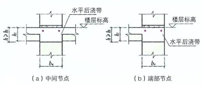
Figure 4: Floor Location Nodes
- For floors enclosing the roof and facade, install a closed post-poured concrete ring beam atop the prefabricated shear wall, with width not less than wall thickness and height at least the larger of slab thickness or 250mm, poured integrally with the composite layer (see Figure 5).
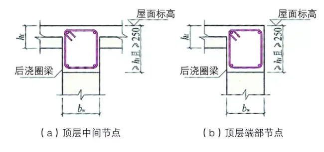
Figure 5: Top Level Position Nodes
- When connecting prefabricated beams to cast-in-place sections, include shear key slots and rough surfaces simultaneously.
- Longitudinal bars of prefabricated shear wall edge components should connect via grouting sleeves arranged in a plum blossom pattern.
- Reserve a 20mm construction joint between the prefabricated shear wall base and structural slab, filled with pressure grouting.
9.5 Mechanical, Electrical, and Construction Reserve and Pre-Embedded Layout
- Reserve electrical sockets on corresponding prefabricated wall panels per decoration drawings, including switches, various sockets, weak current, visual intercom, infrared curtains, and positioning sockets. For SI systems, specify which sockets are excluded from prefabricated panels.
- Install lightning protection embedments at door/window openings and railings for buildings over 60m classified as Class III lightning protection structures.
- When wire boxes are installed on prefabricated panels with downward wiring, reserve accessible hand holes avoiding longitudinal stress bars.
- Adjust refrigerant pipe reserved hole positions to avoid longitudinal and hoop reinforcement.
- Locate fresh air ducts under windows in non-load-bearing walls.
- Prepare formwork for cast-in-place sections between prefabricated walls by reserving perforations or nuts; perforations ease operation but increase sealing workload and leakage risks, while nuts require secure tightening during construction.
- Use climbing frames, triangular protective frames, and landing frames for construction external frames. When using cantilever frames, avoid reserving holes for cantilever rods through exterior walls near edge components with sleeves.
- Maximize door/window opening positions for safety net installations to minimize panel openings.
- Attach tower cranes to reserved cast-in-place wall or floor sections.
9.6 Production Reservation and Pre-Embedded Layout
- Demolding and construction support embedded parts in prefabricated shear wall components produced with flat formwork can be shared, with a safety factor of at least 5. Place embedded parts at least 150mm from wall edges, avoiding longitudinal reinforcement. Maintain consistent height and distance for production ease.
- Transport and lift prefabricated shear wall components using pre-embedded hanging nails. Minimum lengths: 240mm for 2.5t nails, 480mm for 5t nails.
9.7 Prefabricated Shear Wall Panel Numbering and Mold Configuration
- Panels with identical inner blade size, reinforcement quantity, and spacing can share a class number. Outer blade adjustments allow mold universality during production.
- Plum blossom arranged shear wall segments should share a unified starting position for the first sleeve to enable mold adjustments.
Collaboration Across Design, Production, and Construction of Prefabricated Components
- Design should consider production and construction comprehensively, minimizing wet work on-site, improving efficiency, and reducing costs—such as reducing retaining wall masonry, using L-shaped corner components, and applying UHPC decorative components.
- Component processing detailed drawings should optimize mold adaptability and universality. Prepare preliminary mold configuration plans based on drawings and construction schedules to reduce component types and share molds, cutting costs.
- Pre-embedded parts, including molds and fixtures, should be standardized across projects to facilitate inventory management and reuse, amortizing fixture costs over their lifespan.
- Component installation sequence and orientation in detailed drawings should be consistent, ideally unidirectional (e.g., installation facing west for composite panels and interior walls).
- Detailed drawings must comprehensively address connections between exposed steel bars, embedded wire boxes, and cast-in-place parts, avoiding conflicts like collisions between connecting beam bars and reserved holes or wire conduit connections.
Conclusion
In summary, detailed design of precast concrete component processing requires close collaboration across disciplines during construction drawing design, as well as thoughtful component mold optimization, production organization, and installation planning during construction. Early and comprehensive completion of component processing projects is crucial, necessitating proactive involvement from all construction parties. Advancing work milestones and controlling project costs early fosters the rapid growth of the EPC general contracting model.
Article source: China Concrete and Cement Products Association


Must log in before commenting!
Sign Up