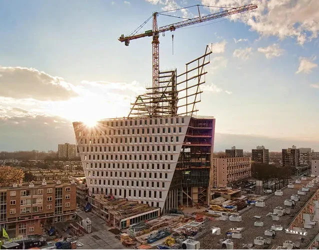
Recently, following the establishment of the comprehensive pipe gallery monitoring center in the High-Speed Rail New City area, Changsha—one of the first pilot cities for comprehensive pipe galleries—has launched three additional monitoring centers. These include the Xiangfu West Road sub-control center, the Beijing Zhuhai East-West Auxiliary Road sub-control center, and the Meixi Lake control center.
Known as the “brain” of the comprehensive pipe gallery, the monitoring center leverages existing monitoring and alarm systems within the gallery to enable intelligent oversight. Once operational, these three centers will provide 24-hour intelligent monitoring and unified scheduling of equipment systems. This covers incoming pipelines and the interior of the pipe gallery through the central monitoring room and four intelligent systems: the environment and equipment monitoring system, security prevention system, communication system, and warning and alarm system.
The pilot project for the underground comprehensive pipe gallery in Changsha spans a total length of 61.4 kilometers, with an investment of around 5.5 billion yuan. It comprises 18 pipe galleries and 4 monitoring centers, totaling 22 projects distributed across the High-Speed Rail New City area, the Meixihu area of Xiangjiang New District, and the High-Tech Zone.
According to the plan, the national pilot construction work will be fully completed by the end of 2018. By 2020, the goal is to build and operate a 100-kilometer comprehensive pipe gallery. Looking ahead to 2030, the city aims to establish a comprehensive underground pipe gallery system covering the entire urban area, featuring approximately 400 kilometers of main and branch pipelines. This network will ensure safety and efficiency in both newly developed urban zones and certain older districts.

Key Points of Comprehensive Pipe Gallery Design
1. The design of urban comprehensive pipe galleries must align with urban land use plans and municipal pipeline planning. It should fully utilize underground space and coordinate with other development activities to maximize social and economic benefits.
2. Construction timing should be coordinated based on pipeline layouts, integrating both short-term and long-term urban planning to ensure synchronization between pipe gallery construction and urban development schedules.
3. Design should expand from city centers and transportation hubs, coordinating urban land use and pipeline planning. The location, direction, and layout of water supply and heating pipelines should be clearly defined based on municipal pipeline plans.
4. Waterproofing design must follow principles of prevention, drainage, interception, and blockage, tailored to local conditions. A comprehensive and effective waterproofing plan should meet standards, usage requirements, technical and economic criteria, and be easy to operate. Structural self-waterproofing forms the foundation, with particular focus on construction joints and deformation joints. Waterproof reinforcement layers should be applied to form a complete underground waterproofing system, ensuring the safety of urban comprehensive pipe galleries.
5. Ancillary facilities must not be overlooked. The design should consider the surrounding environment and coordinate with it, determining appropriate scale, land use, and construction standards for supporting facilities such as control centers, substations, feeding ports, ventilation shafts, and personnel entrances. Fire protection, ventilation, and fire alarm systems should be incorporated, along with supporting structures like bridge brackets to minimize impact on roads and underground spaces.

Key Points for Reinforcement of Comprehensive Pipe Gallery
Soil Reinforcement
1. Grouting reinforcement treatment involves arranging symmetrical plum blossom-shaped holes around the foundation edges. The depth of these holes depends on geological conditions. Using vibration or drilling methods, grouting tubes are inserted to the designed depth. A thick slurry mixed with ordinary Portland cement is injected under pressure into the foundation soil, filling pores, voids, and cavities.
2. During grouting, the slurry encounters minimal resistance, allowing it to penetrate and fill weak seepage areas. It forms irregular vein-like, network-like, and pit-like slurry flows, binding soil particles and crushed stones. After solidification, this creates a stone network with strength, forming a composite foundation that increases density, uniformity, and bearing capacity.
3. For minor cracks with limited settlement and no further development, if the wall columns and pipe gallery structure have sufficient stiffness and strength, surface treatment via mortar filling is adequate.
4. In cases of ongoing uneven settlement and severe cracking, reinforcement should prioritize foundation strengthening before crack treatment. Pile foundation replacement methods can be employed, using cast-in-place piles along both sides of the foundation, installing lifting beams on top, and lifting original foundation ring beams to prevent further sinking.
Main Reinforcement
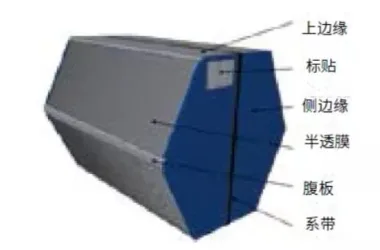
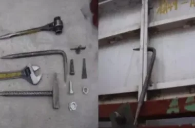
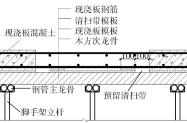
1. Beyond the foundation pit enclosure, the pipe gallery’s main structure involves proper installation of various steel plates. Special attention is needed when constructing the hanging formwork at the pipe gallery’s bottom plate. Steel formwork is typically used for better shaping and firmness, enhancing the overall quality of the pipeline structure.
2. Concrete construction for the pipe gallery’s overall structure poses challenges due to shrinkage and uneven mixing under varying temperature and humidity conditions. Improper casting can cause leaks, cracks, and deformation.
3. To mitigate these issues, admixtures promoting solidification may be added during concrete mixing. This enhances stability, ensuring the pipe gallery remains leak- and crack-free despite temperature and humidity fluctuations.
Key Points of Comprehensive Pipe Gallery Construction
Shield Tunneling Construction Method
This method features excavation, transportation, lining assembly, joint waterproofing, and grouting of shield tail gaps—all conducted under shield protection. Continuous underground water discharge and ground settlement control are required. Due to its technical complexity and comprehensive nature, this method demands high expertise.
Shallow Buried Excavation Method
Characterized by flexibility and adaptability, this method minimally impacts roads, underground pipelines, and adjacent environments. It requires little demolition or land occupation and avoids disturbing residents, making it ideal for renovating existing urban areas where open cut or shield tunneling methods are unsuitable.
Open Cut Cast-in-Place Concrete
The most commonly used construction method, suited for pipeline networks in newly developed cities. This approach enables large-scale operations by dividing projects into multiple sections, accelerating progress. It features low technical difficulty, moderate cost, and reliable quality. However, it requires traffic interruptions during construction.
Top Pipe Construction Method
The pipe jacking method is a trenchless pipeline installation technique similar to shield tunneling. It uses a pipe jacking machine to bore holes and insert prefabricated pipes from the surface into a working well, creating a continuous lining structure. It is suitable for geological conditions such as silty soil, sandy soil, silty clay, and clay in water-rich formations.
Key Points for Safety Monitoring of Comprehensive Pipe Gallery
Real-Time Personnel Positioning Management
The system allows instant tracking of inspection personnel within the pipe gallery, providing dynamic status updates. This information enables management to respond quickly and accurately during emergencies.
Employee Movement Trajectory Query
The management center automatically stores staff movement data on a backend server. Managers can query and replay historical trajectories anytime to supervise, optimize workflows, and enhance efficiency.
Intelligent Attendance Function
By recording location and movement data, the system enables viewing of all workers’ data within specified timeframes, facilitating statistical analysis and intelligent attendance management.
Electronic Fence Intelligent Warning
Electronic fences can be set up in restricted or key inspection areas. Unauthorized entry or prolonged presence triggers immediate system warnings and alerts personnel to leave.
Video Collaboration
The system integrates with on-site monitoring equipment to track real-time images of personnel. In emergencies, the positioning system automatically saves video clips for easy incident tracing.

Key Points of Comprehensive Pipe Gallery Operation and Maintenance
1. Establish a comprehensive operation and maintenance management system that includes automatic fire alarm and linkage, natural gas detection and alarm, linear fiber optic temperature sensing fire monitoring, electrical fire monitoring, and fire telephone systems.
2. Develop detailed maintenance and management protocols covering daily upkeep, duty schedules, safety inspections, data archiving, and overall safety management. Refine all content, processes, and measures involved in pipe gallery maintenance.
3. Implement a robust organizational structure and quality management system for prefabricated R&D. Ensure full-process quality control with dynamic, constraint, feedback, and continuous improvement mechanisms.
4. Carry out daily maintenance and promptly repair subsystem failures. Conduct regular (monthly or quarterly) repairs to address operational issues across the entire system.
5. Perform comprehensive inspections of the pipe gallery at least weekly. Inspection frequency should increase based on seasonal changes, underground structure characteristics, and construction conditions. Install sturdy fences and warning signs as needed, and assign dedicated personnel for supervision if necessary.
Article source: Architectural Technology Magazine


Must log in before commenting!
Sign Up