
Xie Wanglan is the Chief Engineer at Shanghai Tianhua Architectural Design Co., Ltd., specializing in prefabricated concrete structures, high-rise concrete structures, and prestressed concrete structures. He is also the chief editor of the national standard atlases “Construction of Connection Nodes for Prefabricated Concrete Structures (Shear Walls)” and “Construction of Connection Nodes for Prefabricated Concrete Structures (Floors and Stairs).” Additionally, he contributed to the compilation of the “Technical Measures for Design of Civil Building Engineering in China – Prefabricated Building Special Edition,” focusing on prefabricated concrete design for shear wall residential buildings, as well as multiple Shanghai and industry standards.
This article highlights key design aspects of prefabricated concrete frame structures, covering six main areas: assembly structure design process, component composition analysis, design considerations, connection design, detailed design, and case studies. Drawing from years of experience, it summarizes critical points to consider throughout the design process of prefabricated integral concrete frame structures.
1. Prefabricated Structural Design Process
From a design perspective, the cast-in-place construction process differs notably from the prefabricated construction process (see Figure 1). Prefabricated building construction involves component fabrication, which increases the need for detailed component design, also known as deepening design. The main structural construction must align closely with interior design to accommodate the characteristics of prefabricated buildings.
Prefabricated construction requires advanced technology with low tolerance for errors. Mistakes during design can lead to significant losses. Therefore, technical planning at the early stage of the prefabricated construction process is crucial, although often overlooked due to limited experience among design teams and developers.
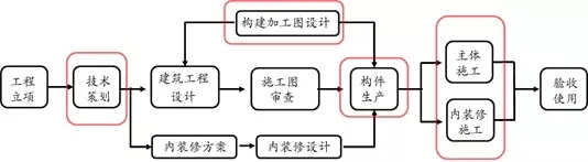
The primary distinction between prefabricated and traditional building design lies in the continuous collaborative design process, spanning from technical planning through main and interior construction. This process demands close cooperation among owners, design professionals, and construction teams (see Figure 2).
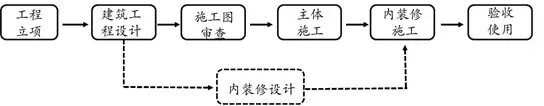
(a) Cast-in-place construction process
(b) Prefabricated construction process
Figure 1: Comparison of cast-in-place and prefabricated construction processes
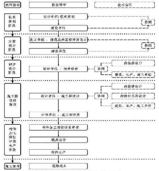
Figure 2: Technological collaboration throughout the assembly design process
The prefabricated construction process involves three key stages (see Figure 3):
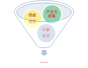
Figure 3: Characteristics of the assembly design process
First, early-stage technical planning is essential, focusing on industry policies. Designers must consider not only policy objectives but also maximize client interests and needs. Clients often have ambitions exceeding policy goals, so balancing policies with industrialization objectives is necessary to define the technical direction. Early technical planning strongly influences the overall technological approach and cost.
Second, technology collaboration is critical throughout the design process. Traditional designs mainly coordinate architecture, structure, equipment, and interiors within design institutes, often delivering basic unfinished buildings with minimal interior design coordination. Prefabricated buildings demand extensive collaboration among design teams, construction units, and production facilities, considering deepening design and manufacturing capacity.
Third, detailed component design is complex and meticulous. Unlike traditional designs where processing plants handle detailed designs, prefabricated buildings require design institutes and processing plants to manage these tasks, which involve many considerations distinct from traditional roles. Prefabricated building design must address production, lifting, and on-site construction requirements, making the process more involved.
2. Composition Analysis of Prefabricated Frame Structural Components
1. General Requirements for Assembly Integral Structural Design
- Architectural design should prioritize fewer specifications with more combinations.
- Assembly and integration technologies should be adopted for main structures, decoration, and equipment pipelines.
- Design should comply with standards for coordinated building modules.
- Industrialized and standardized products are recommended for enclosure structures and building components.
- A flat layout with large openings and depths is advisable.
- Regular floor plans and elevation layouts are preferred.
Structural design is inherently complex, but prefabricated buildings require stepwise solutions through this complexity. A key starting point is adopting an industrial mindset, often called conceptual design, which balances cost and construction convenience. For example, standardization reduces costs by limiting component variety. While traditional designs often use 2-3 meter spans with thinner slabs, prefabricated composite floor slabs typically suit 4-6 meter spans, sometimes larger.
2. Maximum Applicable Height of Assembled Integral Structures
When designing, it’s crucial to evaluate if a prefabricated structure suits the building. Figure 4 shows maximum applicable heights for prefabricated integral and cast-in-place structures. If main lateral force-resisting nodes are cast-in-place concrete, they must meet stress requirements. For prefabricated shear wall structures, if the shear wall component at the base bears over 50% of total floor shear, the maximum height is reduced; if over 80%, the maximum height aligns with values in parentheses in Table 6.1.1.
Key differences include:
- Seismic fortification intensity of 9 degrees is not applicable to prefabricated concrete structures.
- The maximum height for prefabricated frame and frame cast-in-place shear wall structures matches cast-in-place structures.
- The maximum height for prefabricated shear wall structures is reduced.
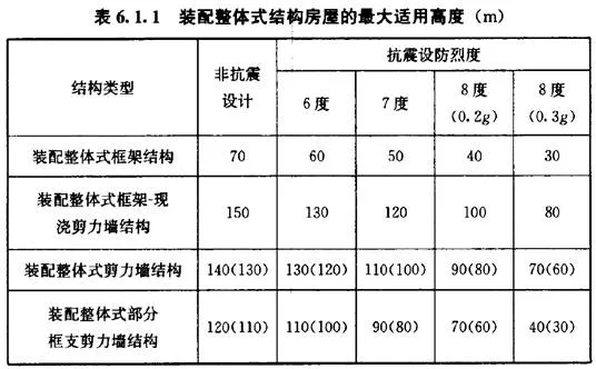
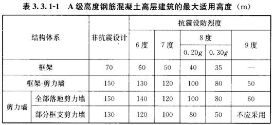
Figure 4: Maximum applicable heights for assembled integral and cast-in-place structures
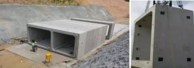
3. Prefabricated Components for Frame and Frame Shear Wall Structures
Prefabricated components include columns (fully prefabricated), beams (composite or fully prefabricated), slabs (composite panels with or without formwork and support, fully prefabricated slabs), stairs, exterior wall panels (single wall or sandwich insulation), parapets, and more (see Figure 5). Note that exterior wall panels here do not refer to shear walls, which must be cast-in-place in frame shear wall systems as per regulations. This section focuses primarily on lateral force-resisting components. A prefabricated building without using a prefabricated main structure falls short of true prefabricated building standards.
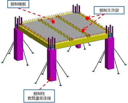
(a) 3D schematic of prefabricated frame structure
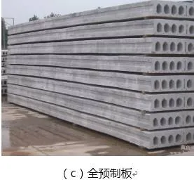
Figure 5: Prefabricated components of frame and frame shear wall structures
4. Negative List for Prefabricated Component Layout
Not all structures are suitable for prefabricated components. Standards guide designers who often rely on these to regulate their work. Current regulations specify:
- The shear wall portions of assembled integral frame shear wall structures should be fully cast-in-place and are unsuitable for prefabricated components.
- According to the “Technical Specification for Prefabricated Concrete Structures” (JGJ 1-2014), high-rise prefabricated integral structures must follow:
- Basements should be cast-in-place concrete.
- Reinforced shear walls at the base should be cast-in-place concrete.
- First-floor columns in three-frame structures and top-floor floor structures must be cast-in-place.
- Basement roofs should be cast-in-place concrete, not prefabricated.
- Avoid tension at horizontal joints of prefabricated columns; in such cases, assembly is not suitable.
- The bottom frame support layer should not exceed two stories.
- The frame support layer and adjacent upper floors should be cast-in-place.
- Transfer beams and columns must be cast-in-place for non-frame supported shear wall structures.
- Composite floor slabs are recommended.
- Cast-in-place slabs should be used for structural transition floors, complex layouts, large openings, and basement floors embedded into the upper structure.
- Avoid tension at horizontal joints of prefabricated columns.
5. Prefabrication Rate of Frame and Frame Shear Wall Structures
The prefabrication rate is calculated according to the “Notice of the Shanghai Municipal Housing and Urban Rural Development Management Committee on the Calculation Rules for Prefabrication and Assembly Rates of Prefabricated Buildings in the City (Trial)” (HuJian Building Materials No. AI-B_SC_0_601) (see Figure 6). Many local authorities specify two key indicators for prefabricated buildings: the prefabrication rate and the assembly rate.
If all components of frame and frame shear wall structures are prefabricated, the prefabrication rate coefficient—calculated using formwork-free floor slabs—can reach 73% for frame structures and 78% with unsupported slabs. This coefficient is weighted by component weight, not concrete volume, per Document No. 601. Under suitable design conditions, even higher prefabrication rates are achievable.
For frame shear wall structures, a full prefabrication approach yields a coefficient around 80%, corresponding to an approximately 40% prefabrication rate, meeting Shanghai’s standards. This calculation excludes external wall panels and partition walls, which could further increase prefabrication rates, although using external wall panels limits prefabrication of other components.
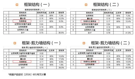
Figure 6: Prefabrication rates for frame and frame shear wall structures
Prefabricated frame structures feature three component types:
- By body type: one-dimensional, two-dimensional, or three-dimensional components. Currently, one-dimensional members dominate, primarily for rod system frame structures.
- By node type: prefabricated nodes (Figure 7 (a)–(c)) or cast-in-place nodes (Figure 7 (d)).
- By column form: single or cross layers. One-dimensional members are preferred for ease of fabrication, installation, and tolerance for adjustment at nodes, exemplified by cross-story truncated columns in Figure 8. Three-dimensional components require high installation precision and pose challenges in production, space usage, transport, and maintenance.
(a) Prefabricated Node 1
(b) Prefabricated Node 2
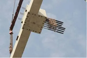
(c) Prefabricated Node 3
(d) Cast-in-place nodes
Figure 7: Prefabricated and cast-in-place nodes of prefabricated frame structures
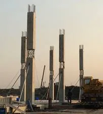
Figure 8: Cross-layer truncated one-dimensional component
6. Floor Structure Layout
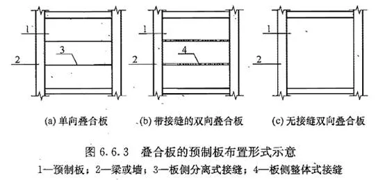
Floor structures are arranged as one-way or two-way slabs, influencing the main structural design. Three key considerations guide layout:
- Component production,
- Transportation and lifting,
- Connection between components.
These differentiate prefabricated from cast-in-place concrete structures, as outlined in Figure 6.6.3 of JGJ 1.
3. Design and Analysis of Prefabricated Frame Structures
Design Method
Standards specify that prefabricated frame structures are equivalent to cast-in-place concrete frames in performance, not necessarily in connection or construction methods. Their nodes must meet cast-in-place structure requirements, as stated in Article 7.1.1 of JGJ 1:
“Unless otherwise specified, assembled integral frame structures can be designed as cast-in-place concrete frame structures.”
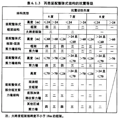
Seismic Grade
Seismic resistance levels are nearly identical, with minor differences in building height limits, detailed in Table 6.1.3 of JGJ 1.
Structural Layout and Component Design
A strong industrial mindset remains essential in structural layout. Prefabricated buildings require alignment in column grids and consistent beam and column positioning. Unlike cast-in-place structures, placing components along edges is discouraged because it complicates node connections. Instead, components are ideally placed centrally.
Designs should incorporate a height difference at the bottom of intersecting beams to avoid steel bar interference at nodes, facilitating on-site assembly. Large open spaces benefit from larger slab spans to reduce beam count and simplify component types.
For node connections, consider:
- Appropriate component cross-sections to avoid excessive reinforcement (e.g., column width is 1.5 times beam width in cast-in-place, but less emphasized in prefabrication).
- Use of high-strength steel bars to reduce reinforcement quantity.
- Reinforcement methods employing large diameter bars with fewer strands and wider spacing.
Analysis Model and Parameters
Prefabricated concrete structures differ from cast-in-place concrete in several ways:
- Beam support model: Hinged or rigid connections are chosen based on connection convenience. Hinged supports are preferred for assembly beams but not for frame beams. JGJ 1 emphasizes that the overall structural calculation model should reflect the connection types and performance.
- In-plane stiffness and beam stiffness coefficient: Prefabricated bottom slabs contain joints, so infinite in-plane stiffness assumptions used in cast-in-place are not fully applicable. The beam stiffness increase coefficient ranges from 1.3 to 2.0, lower than cast-in-place.
- Periodic reduction factor: This accounts for enclosure structure influence on main structural stiffness. Due to uncertain exterior wall panel connections, this factor is applied cautiously.
- Floor slab layout: Load transmission paths may vary; one-way slab arrangements affect force transmission and require appropriate connection designs to approximate two-way slab behavior.
- Concrete protective layer thickness: Steel bar connection requirements necessitate consideration of sleeve diameters causing offset inside components, which can be significant (e.g., 70mm near column center steel bar).
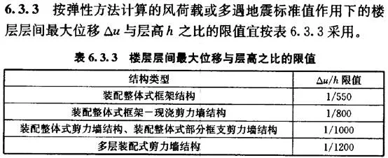
Displacement Angle Limit
Displacement limits in prefabricated concrete buildings align with those for cast-in-place structures. For multi-layer prefabricated shear wall structures, stricter limits (1/1200) apply due to weaker connections and varied rigid wall behavior, as outlined in Article 6.3.3 and Table 6.3.3 of JGJ 1.
4. Connection Design of Prefabricated Frame Structures
1. Joint Section Bearing Capacity
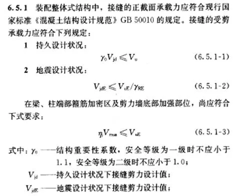
The key difference in connection design lies in methods distinct from cast-in-place concrete. Joint cross-sectional bearing capacity must comply with the national standard “Code for Design of Concrete Structures” GB50010. Shear bearing capacity must be verified alongside durability and seismic requirements. Generally, joint bearing capacity should not be less than member capacity, so only shear capacity verification is necessary.
Shear capacity increase factors are 1.2 for seismic grades 1 and 2, and 1.1 for grades 3 and 4. Reinforcement zones require strong joints and weak components, especially at beam and column ends and shear wall bases, as detailed in Article 6.5.1 of JGJ 1.

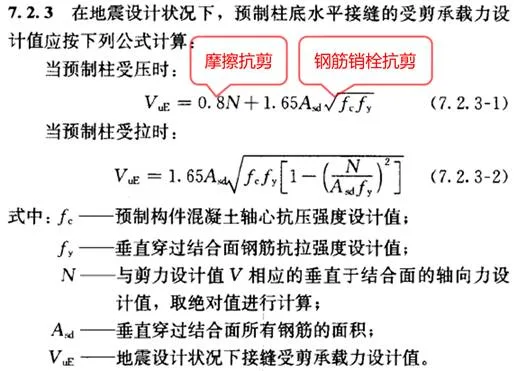
2. Shear Bearing Capacity Verification of Horizontal Joints at Prefabricated Column Bases
Under seismic design conditions, horizontal joints at prefabricated column bases bear shear forces from frictional resistance and steel bar bolts if under compression. Tensioned prefabricated columns lack frictional shear resistance. Tension also influences steel bolt shear resistance, with modified formulas detailed in Article 7.2.3 of JGJ 1.
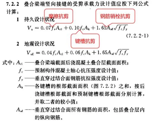
3. Shear Bearing Capacity of Vertical Joints at Composite Beam Ends
Shear capacity at vertical joints includes contributions from the cast-in-place composite layer, keyway shear resistance, and steel bolt shear resistance. Two conditions apply: long-term stress and seismic design, with seismic capacity approximately 60% of long-term capacity. Details are in Article 7.2.2 of JGJ 1.
4. Shear Bearing Capacity Calculation of Horizontal Composite Surfaces on Composite Beams
The calculation follows the formula below, accounting for concrete bonding shear resistance and steel reinforcement shear resistance:
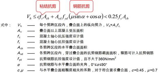
5. Shear Bearing Capacity of Composite Slab Horizontal Surfaces Without Shear Reinforcement
Even without steel reinforcement, laminated panels generally meet shear bearing requirements due to their large overlapping surface areas. The following formula can be used for reference.
6. Joint Surfaces
According to JGJ 1:
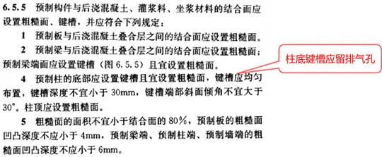
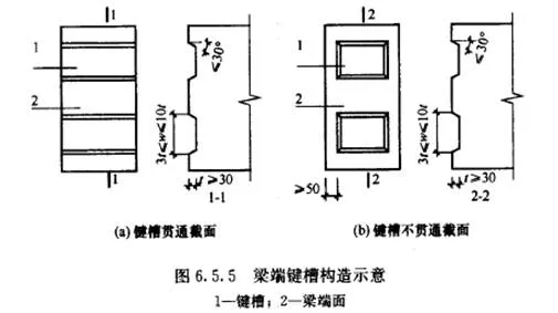
Joint surfaces must be either roughened or include keyways, or both. Prefabricated beam ends require keyways per specifications, which may extend through the beam width. Rough surfaces should cover at least 80% of the bonding area, with roughness depths of at least 4mm on panels and 6mm on beam, column, and wall ends.
On-site observations reveal many rough surfaces are inadequately prepared, often using steel plates with only 1-2mm depth, insufficient by standards. The design calculations typically do not factor joint surface quality, assuming minimal shear resistance from smooth surfaces, adopting conservative safety margins. Some manufacturers achieve standard-compliant rough surfaces via water washing.
7. Reinforcement Connection Methods
Various steel bar connection methods are permitted for integral structures under current national standards, as outlined in Article 6.5.2 of JGJ 1. For prefabricated columns, longitudinal steel bar connections follow regulations in Article 7.1.2:
- For buildings up to 12 meters or up to 3 floors, sleeve grouting, anchor lap, welding, and similar methods are acceptable.
- For taller buildings, sleeve grouting is recommended.
8. Joint Materials
Concrete or grout materials used in joints must have strength grades not lower than the prefabricated components themselves. Article 6.1.12 of JGJ 1 specifies this requirement. For multi-layer shear wall structures, grout strength for horizontal wall panel joints must exceed the connected components’ concrete strength.
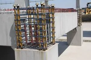
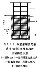
9. Prefabricated Column Connection Nodes
Figure 7.3.5 in JGJ 1 illustrates the densified hoop reinforcement zone structure at column bottoms when steel bars are connected via sleeve grouting. Additional reinforcement details for post-poured column bottoms can be found in Figure 5.6.12 of related materials.
10. Composite Beam Connection Nodes
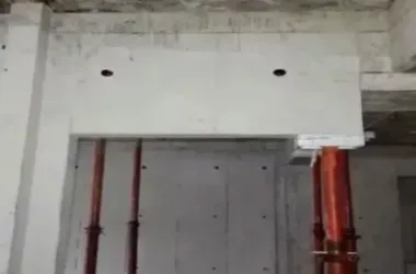
Figure 7.3.3 in JGJ 1 provides schematic diagrams for composite beam connection nodes. Figure 9 below shows an on-site construction example.
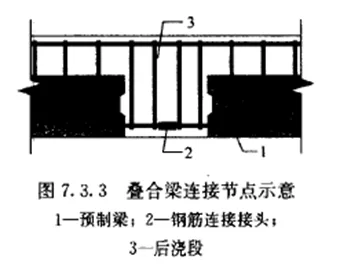
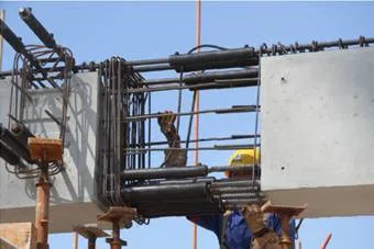
Figure 9: On-site engineering example of composite beam connection
11. Post-Poured Beam-Column Nodes
Beam-column connections typically use cast-in-place concrete nodes, or post-poured nodes. Figure 7.3.8-1 in JGJ 1 illustrates the node structure for mid-level prefabricated columns and composite beam frames. If beams on both sides share equal heights without adjustment, steel bars will intersect at the node, necessitating careful avoidance and installation sequencing to prevent bar bending.
Multi-layered steel bars aggravate crossing and bending issues. Therefore, preferred designs feature beams of differing heights to facilitate steel bar avoidance. Beam-column joints must prioritize steel bar clearance.

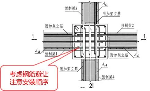
Figure 10: Prefabricated frame structure connection design – post-poured beam-column node construction (Part 1)
At the top edge or corner column nodes, steel bars are extended upward to avoid unsuitable downward bending, especially in cast-in-place beam-column edge nodes requiring significant downward bending length. Without considering this extension, reinforcement placement and prefabricated column completion become problematic, causing construction challenges.
At node K1-15 (Figure 11), waist bars installed inside beams are placed later due to bidirectional beams. Though technically feasible to install after other elements, waist bands are not ideal. Avoiding anti-torsion waistbands is preferable; if necessary, post-installation should be considered to prevent lifting interference. Alternative designs place beam reinforcement outside nodes or in other directions to mitigate torsion. Designing beams without torsion is challenging; hinge connections at secondary beam ends help reduce torque on main beams and eliminate the need for waist reinforcement.
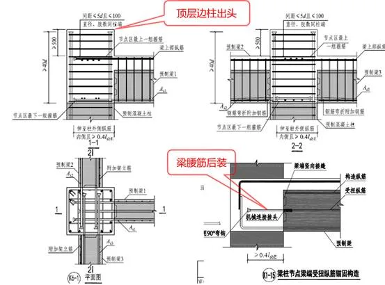
Figure 11: Prefabricated frame structure connection design – post-poured beam-column node construction (Part 2)
Figure 12 illustrates connection structures within the post-poured sections outside longitudinal reinforcement nodes at beam bottoms.
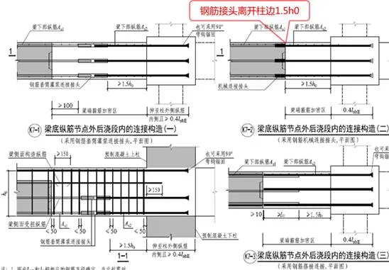
Figure 12: Prefabricated frame structure connection design – post-poured beam-column node construction (Part 3)
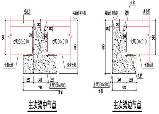
12. Primary and Secondary Beam Connection Nodes
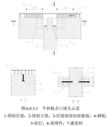
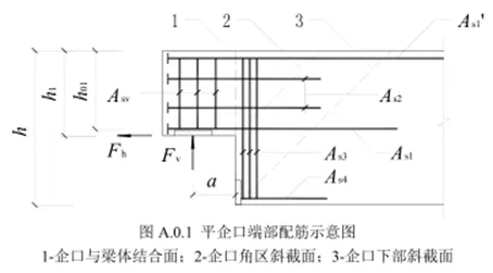
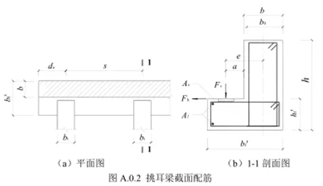
Figure 7.3.4 in JGJ 1 depicts schematic construction of primary and secondary beam node connections. Figure 13 presents an on-site engineering example. Additional references include Figures A.0.3-1 (cow’s shoulder board joint), A.0.1 (flat joint end reinforcement), and A.0.2 (cantilever beam reinforcement) in other materials.
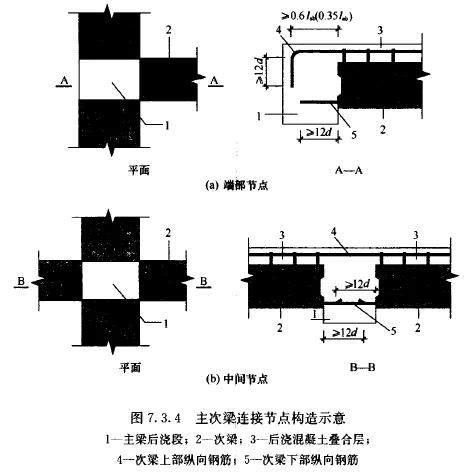
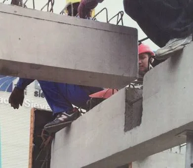
Figure 13: On-site example – primary and secondary beam connection nodes
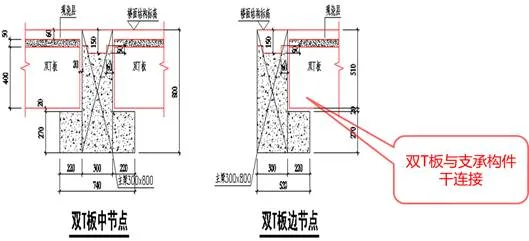
13. Laminated Panel Joints
Panel joint connections are detailed in JGJ 1’s Figure 6.6.4, showing end and side support structures. Figure 6.6.6 illustrates integral joints of double-sided composite panels, noting steel bar interference during installation. The national building standard atlas (G310-1~2, 2015 edition) presents the post-pouring strip form (Figure 14), which avoids interference but requires wider post-pouring strips.
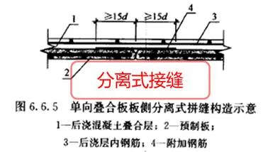
Single-sided composite panel side separation joints are shown in Figure 6.6.5 of JGJ 1, imposing specific prefabrication or cast-in-place strip requirements for panel joints.
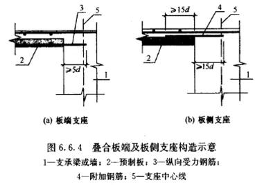
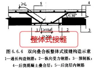
Figure 14: Post-pouring strip form panel joint
5. Detailed Design of Prefabricated Frame Structures
The core principle of detailed design is to meet production and installation requirements. Prefabricated frame structures differ from cast-in-place concrete by requiring temporary design condition considerations. JGJ 1 mandates that components undergo verification for short-term conditions such as production, transport, stacking, and installation per current standards.
This results in notable design condition differences. Specific prefabricated building scenarios—lifting, embedded parts, and equipment pipeline integration—must be addressed in detailed design. Consequently, detailed design drawings are complex, as shown in Figure 15.
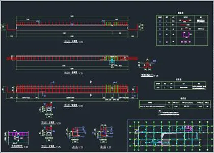
(a) Prefabricated beam reinforcement diagram
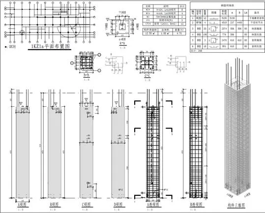
(b) Prefabricated column reinforcement diagram
Figure 15: Examples of detailed design for prefabricated frame structures
6. Case Studies of Prefabricated Frame Structures
(1) Case 1: Comprehensive Office Building in Hefei
Overview
This multi-story building covers 6,100 m², achieving a high prefabrication rate of approximately 83%. The client explicitly required a high degree of prefabrication to showcase prefabricated technology, aiming for maximal assembly use.
Structurally, the standardized 6.9m × 6.9m column grid underpins the layout and quantity of prefabricated composite beams and panels, limiting slab span and spacing variations to three types, reducing component variety. The layout is square with an industrialized facade design emphasizing fewer specifications and more combinations, meeting personalized building needs.
Project details:
- Building area: 6,100 m² with 5 floors above ground, total height 22.1 m.
- Functions: office, exhibition, and factory support rooms.
- Floor heights: 5.0 m at bottom level; approximately 4.2 m for levels 2–5.
- Facade: glass curtain wall and external prefabricated concrete wall panels.
- Structural system: assembled integral frame structure, seismic grade 3.
- Prefabrication scope: external wall panels, columns, composite beams, prestressed hollow slab composite floors (some steel truss composite panels), stairs, plain concrete interior walls, aerated concrete strip boards, parapet walls.
- Prefabrication rate: about 83% for the individual building.

Figure 16: Rendering of Hefei project
Architectural Design – Block Analysis
- Volume segmented across 6,100 m².
- Incorporation of a green atrium with double-sided lighting to resolve poor mid-depth lighting in the 24 m deep building.
- The skylight atrium enhances natural lighting, reduces electricity use, improves energy efficiency, and creates a pleasant environment.
- Visual and spatial communication is enhanced, adding aesthetic value.
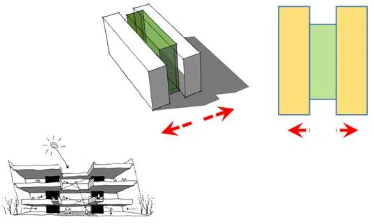
Figure 17: Architectural design – block analysis
Architectural Design – Standardization of Column Grid
The 6.9m × 6.9m standardized grid determines prefabricated composite beam and slab layouts, limiting span and slab types and reducing component diversity.
Figure 18: Architectural design – column grid standardization
Architectural Design – Graphic Design
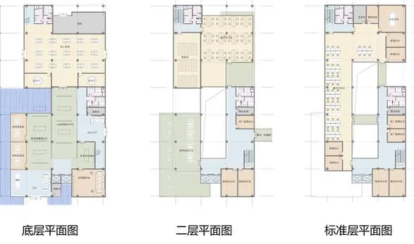
Figure 19: Architectural design – graphic design
Architectural Design – Facade Design
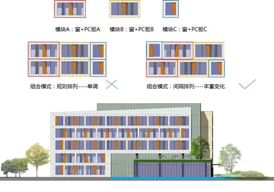
Figure 20: Architectural design – facade design
Prefabricated System
As a prefabricated assembly demonstration project, the design maximizes prefabricated component scope to showcase industrialized construction advantages and reduce on-site wet work. The prefabrication scope includes:
- Frame columns (from -0.200 m to roof level).
- Main and secondary beams (from second floor to roof), using composite beam methods.
- Floor slabs (partially steel truss composite and prestressed hollow slab composite).
- Interior partitions (precast concrete walls, precast ceramic aggregate concrete walls, aerated concrete strip boards).
- Stairs (prefabricated staircases and door frames).
- Exterior facade (prefabricated wall panels and glass curtain walls).
System Characteristics
- Prefabricated frame columns extend from foundation to roof, with enlarged bottom column cross-sections (Figure 21a).
- Office rooms omit secondary beams, using prestressed hollow slab composite panels without formwork or support, enhancing construction efficiency (Figure 21b).
- Large-span frame beams partially use pre-tensioned prestressed prefabricated composite beams.
- Exterior facade combines staggered prefabricated wall panels and glass curtain walls.
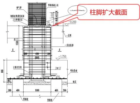
(a) Enlarged bottom column cross-section
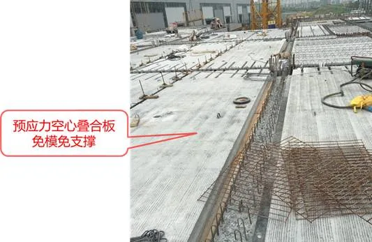
(b) Prestressed hollow composite panels without formwork or support
Figure 21: Main characteristics of prefabricated structural system
(2) Case 2: Large Commercial Shopping Center in Shanghai
Project Overview
This large commercial shopping center integrates retail and leisure, located in Minhang District, Shanghai. The building footprint measures approximately 183m x 167m, with a column grid of 8.4m x 8.4m. An inner courtyard-style atrium enhances spatial atmosphere but complicates prefabrication in certain areas.
Key parties include China Construction Shanghai Institute (main building design), China Construction Eighth Engineering Division (general contractor), and Shanghai Tianhua (PC deepening design). The rendering and overview are shown in Figure 22.
▲ Rendering
▲ Project overview
Figure 22: Project rendering and overview
Due to various factors, deepening design began late. The owner initially used other industrialization measures to achieve prefabrication but failed to meet Shanghai’s assembly rate requirements. The project targets a 30% prefabrication rate.
The pink area in Figure 23 uses a double T-plate floor plan; other areas use flat plate layouts.
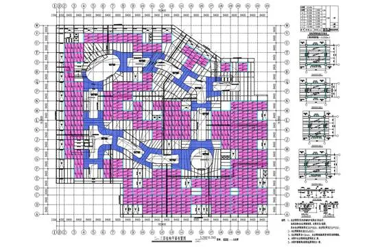
Figure 23: Typical floor structure layout plan
Upper Structure Characteristics
- Plan dimensions: 167m width x 183m length, very large scale.
- Four floors above ground, with some areas having five floors.
- Main roof elevation: 20.900m; cinema roofs at 23.750m; indoor-outdoor height difference 0.3m.
- Total building height under 24m, designed as multi-story.
- Large commercial atrium and mezzanine cinema floors include large openings, weakening effective floor slabs.
- Multiple large cantilever and large-span beams.
- Structural system: assembled integral frame with all cast-in-place columns.
- Prefabrication rate about 30%, below Shanghai’s current 40% standard.
- Early design decisions fixed column grid layout; commercial plan and facade remain flexible, limiting large-scale prefabrication.
- Prefabricated stairs and composite beams (prefabricated with cast-in-place composite layers) are used.
- Standard units use prefabricated double T composite plates; irregular areas use steel truss composite plates in flat plate form.
- All suitable components are prefabricated except those limited by column grid layout or lifting constraints.
- On-site report by China Construction Eighth Engineering Division indicates 5,708 prefabricated components used, mainly frame beams, secondary beams, composite panels, stairs, and double T-plates (see Table 1).
Table 1: Statistics of PC Components
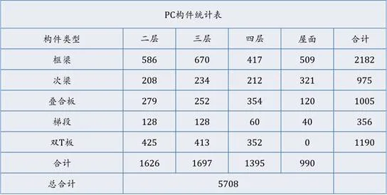
Data source: China Construction Eighth Engineering Division – On-site Construction Organization Plan Report
Comparison and Selection of Prefabricated Composite Panels
The project’s key technical feature is the use of double T-plates for floor slabs. An economic comparison between prefabricated double T composite slabs and reinforcement-free truss composite slabs is shown in Figure 24.
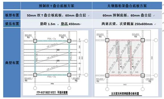
(a) Comparison and selection of prefabricated double T composite bottom plate scheme and reinforcement-free truss composite bottom plate scheme
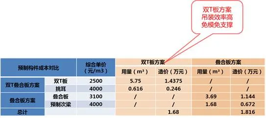
(b) Cost comparison
Figure 24: Scheme and economic comparison
The double T-laminated panel scheme is slightly more cost-effective than the truss composite panel scheme, though prices depend on local supply. Double T-plates require no molds or supports and offer higher lifting efficiency. The truss composite panel scheme involves two secondary beams and multiple panels, complicating lifting and slowing construction.
The project’s double T-plate differs from the standard atlas version (see Figure 25) by featuring ribs and protrusions of equal cross-section. This ensures uniform end sizes and thicknesses, enhancing indoor aesthetics and enabling mold reuse for different span connecting plates.
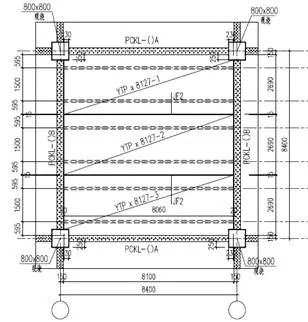
(a) Double T-board layout plan
(b) Secondary beam support method
Figure 25: Standard column grid double T-plate
(a) Double T-plate support method
(b) Secondary beam support method
Figure 26: Construction methods for double T-plate and secondary beam support
Layout of Tower Cranes and Truck Cranes
Due to heavy component weights, double T-plates (~5 tons) are lifted by tower cranes, while beams exceeding 10 tons require truck cranes. The project uses a combination of both crane types (see Figure 27).
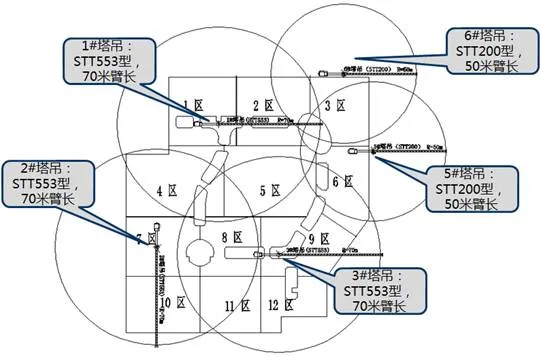
(a) Tower crane layout plan
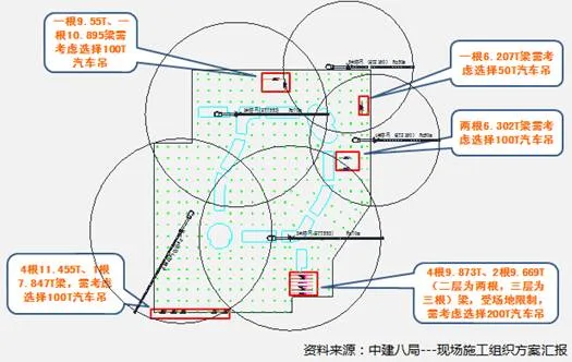
(b) Truck crane arrangement
Figure 27: Tower and truck crane layouts
Construction Site
Figure 28 showcases typical on-site assembly scenarios:
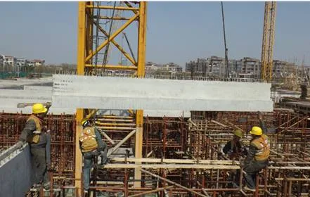
(a) Stacked beam hoisting
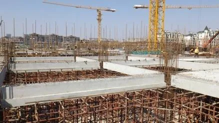
(b) Composite beam
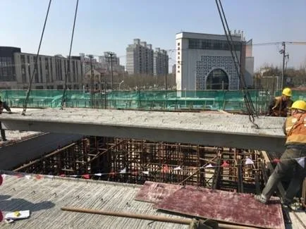
(c) Double T-plate lifting

(d) Double T-plate connection
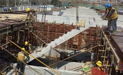
(e) Prefabricated staircase hoisting
Figure 28: On-site construction scenes of prefabricated components
Organized and edited by Li Wenyang and Liu Shan


Must log in before commenting!
Sign Up