Chapter 3: Lifting Operations of Prefabricated Concrete Components
Content Summary
The lifting operation of prefabricated concrete components is crucial for the lifting, positioning, and adjustment of these elements throughout the construction process of prefabricated buildings. It facilitates the temporary positioning of the components on site. This chapter provides a detailed overview of lifting operations, covering the types and characteristics of commonly used lifting machinery, selection criteria for lifting equipment, and specific procedures for lifting various prefabricated concrete components such as wall panels, floor slabs, beams, and stairs.
Initially, the chapter addresses the selection and coordination of equipment and tools necessary for lifting prefabricated concrete components, establishing relevant guidelines. It then comprehensively explains the lifting processes, operational methods, temporary fixation devices, and key considerations for handling different types of prefabricated concrete elements.
3.3 Lifting Operation of Precast Concrete Wall Panels
3.3.1 Methods and Reinforcement Measures for Lifting and Binding Prefabricated Components
1) Binding Methods for Prefabricated Components
Binding of prefabricated components can be categorized into two types: symmetrical binding and asymmetrical non-binding.
2) Reinforcement during Transportation, Flipping, and Hoisting
For components exhibiting lateral stiffness differences, temporary braces can be installed for reinforcement. These braces are attached to the components using embedded nuts. During transportation, flipping, and lifting, support points are positioned on the reinforced rods to prevent deformation of the components.
3) On-site Flipping Operation Requirements
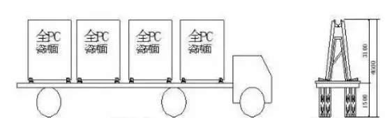
Flipping is essential for transporting prefabricated components to the construction site for stacking. Typically, four slings are used—two long, two short—and two manual hoists. Before lifting, ensure all slings are adjusted to equal lengths and securely tightened. Lift the components off the ground or assembly surface, then gradually straighten them by loosening the manual hoists while lifting. Finally, loosen the hoist sling beneath the components and place them onto the steel frame.
3.3.2 Placement and Temporary Fixation of Prefabricated Components
Before lifting, the installation team must verify that the model and specifications of the components are correct and that the surface quality meets standards. After lifting the components off the ground, level the installation surface horizontally using a chain hoist. Secure cable wind ropes at the base of the components.
Mark the positioning axis at the installation site and set up temporary supports. Hoist the components to their designated positions, align them with the axis, and bolt them to the temporary supports. Install adjustable temporary slant supports at the top ends of the components.
Due to the large surface area exposed to wind, use a slow positioning mechanism to gently lower the components during hoisting. To control rotation, tie cable wind ropes at the base to ensure smooth placement. To counteract shaking during tower crane hoisting, temporary guide devices may be installed on both the components and installation surfaces, ensuring precise one-time positioning.
After temporary fixation, the lifting commander must confirm that the components are securely connected before the lifting hooks are released.
3.3.3 Operation Requirements for Lifting Personnel
- Before lifting, inspect all mechanical rigging, fixtures, and lifting rings for compliance, and conduct a trial lift.
- Unified command and signaling must be maintained during the lifting process.
- When using tools such as pry bars, apply force evenly and slowly, ensuring the fulcrum is stable to prevent accidents.
- Do not loosen ropes or unhook suspended components before calibration, welding, or fixation is complete.
- Components should not be suspended or stopped midway for extended periods during lifting.
- Steel wire ropes must be kept clear of electrical lines, welding grounding wires, and should not rub against hard surfaces.
3.3.4 Hoisting Process of Precast Concrete Wall Panels
- Attach lifting machinery to the prefabricated components. The number and position of lifting points depend on the length and cross-sectional shape of the wall panel. Lock the steel wire rope clamp ring at each lifting point, and connect the lifting machinery hook to the clamp ring. The lifting rope should be positioned directly above each lifting point.
- Check the stability of the connection between the hook and suspension ring, ensuring the suspension chain is evenly stressed. Lift slowly and pause once the lifting rope is taut to inspect the automatic snap ring and prevent accidental detachment. To minimize swinging during placement, attach a slip rope at the bottom of the wall panel. Operators should maintain a safe distance and verify all connections before lifting.
- When the wall panel is lifted approximately 500mm above the ground, pause briefly to remove protective pads and support legs. Then, under the signaler’s command, lift the panel to the floor level for positioning. Note that tower crane lifting and arm rotation should not occur simultaneously for safety.
- Once positioned, slowly lower the panel onto the installation surface. Verify the panel number, adjust orientation, and have two personnel guide it to ensure precise alignment. Install temporary supports and fixations to secure the panel. Remove suspension hooks only after temporary supports are in place.
- After installation, perform vertical corrections, fix upper and lower support throwing rods, and securely weld them to the embedded floor parts. Finally, seal the panel joints with adhesive tape strips.
3.4 Hoisting Operation of Prefabricated Concrete Floor Slabs
3.4.1 Prefabricated Composite Floor Lifting Process
1) Installation of Suspension Points
Each composite floor slab requires four lifting points located at the junction of the upper chord and web reinforcement of the lattice beam, positioned between one-quarter and one-fifth of the slab length from the slab ends. These points must be evenly stressed to prevent excessive load on any single point. After horizontal adjustment, the slab should be placed on its support.
Suspension points are established by embedding steel reinforcement rings.
Table 3-9: Data Sheet for Lifting Point Settings
| Width (mm) | Length (mm) | Distance from Edge (mm) |
|---|---|---|
| 1200–2400 | 3000/3300 | 600 |
| 3600 | 700 | 3900 |
| 800 | 4200 | 900 |
| 4500 | 1000 |
Due to their relatively thin and large size, prefabricated composite floor slabs require professional lifting equipment to avoid uneven stress that could damage the structure. For slabs with any side longer than 2.5 meters, six lifting points are recommended. For spans exceeding 6 meters, eight suspension points should be used to balance the load.
2) Support Frame Setup Before Hoisting
A support frame, similar to those used for prefabricated beams, must be erected beneath the floor slab before hoisting.
The first support should be placed within 0.2 to 0.5 meters from the slab edge. Support installations must be vertical, with triangular brackets firmly clamped. Maximum spacing between supports should not exceed 1.8 meters. For spans over 4 meters, the midpoint of the room should be slightly arched.
The I-beams in the support system should be oriented perpendicular to the direction of the composite floor’s lattice beams.
Two main types of support frames are used: independent steel columns and folding tripods.
Independent Steel Columns
These consist of outer and inner pipes, fine-tuned threaded pipes, and nuts. They function as adjustable vertical supports for prefabricated horizontal structures, capable of bearing the self-weight of beams, slabs, and construction loads. The inner pipe features holes every 100mm for height adjustment via a nine-character hook, while the outer pipe includes a threaded section matched with a fine adjustment nut providing up to 130mm of precise height adjustment. The total adjustable height and load capacity vary based on project requirements.
Folding Tripods
These have welded pipe legs connected by a central eccentric lock. When deployed, the tripod legs spread and the lock is hammered to secure the support rods, providing independent and stable support. For transport, the legs retract, allowing easy manual handling and storage in a box for centralized lifting.


Must log in before commenting!
Sign Up