Source: Construction Industry Celebrity Circle
Content Summary
The lifting operation of prefabricated concrete components is crucial throughout the construction of prefabricated buildings. It involves lifting, positioning, and adjusting concrete elements, completing their temporary placement. This chapter provides a comprehensive overview of lifting operations, covering commonly used lifting machinery types and characteristics, equipment selection, and specific procedures for various prefabricated components such as wall panels, floor slabs, beams, stairs, and others.
The chapter begins with guidelines on equipment and tool selection for lifting prefabricated concrete components. It then details the lifting processes, operational methods, temporary fixation techniques, and key considerations for different component types.
3.7 Lifting Operations of Other Precast Concrete Components
3.7.1 Prefabricated Column Lifting Operation
1. Construction Process of Prefabricated Column Hoisting (see Figure 3-33):
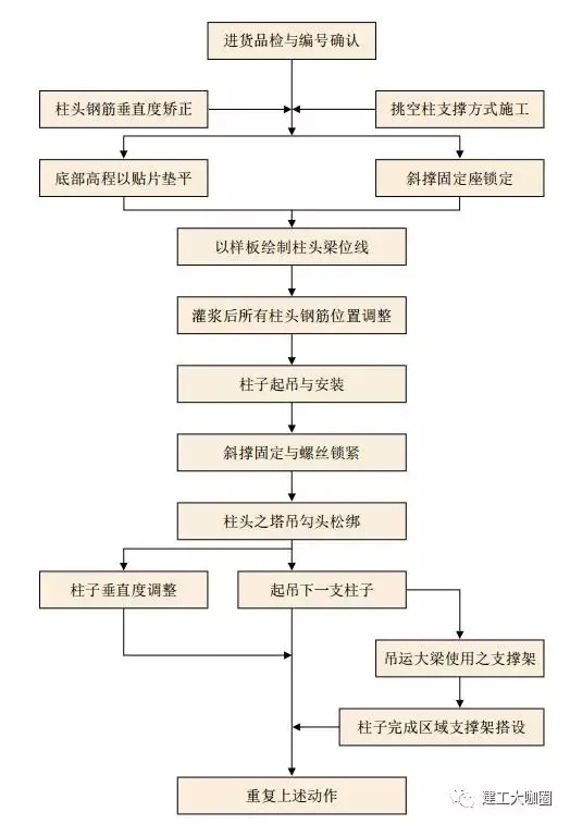
Figure 3-33: Construction process of prefabricated columns
2. Preparation Before Construction:
(1) Verify the position and elevation of the lower reinforcement at the column connection. Ensure the bottom concrete surface is clean, and mark the column location with a snap line (see Figure 3-34).
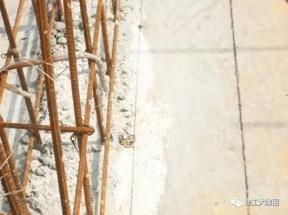
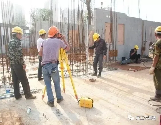
Figure 3-34: Snap line marking for prefabricated column position
(2) Prepare installation equipment such as diagonal supports, fixing irons, bolts, and elevation adjustment iron sheets (available in four standard thicknesses: 10mm, 5mm, 3mm, and 2mm, which can be combined) (see Figure 3-35). Additional tools include lifting devices, verticality measuring rods, and aluminum or wooden ladders.
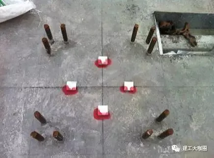
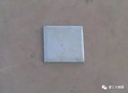
Figure 3-35: Elevation adjustment iron sheets
(3) Confirm whether the position of the column head support beam has been marked.
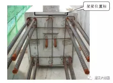
Figure 3-36: Beam position layout
(4) Verify installation direction, component number, lifting points, and component weight.
3. Prefabricated Column Hoisting Construction:
(1) Review benchmark layout, column boundary layout, and steel bar positioning. Clean the interior of the column sleeve using high-pressure air—avoid water cleaning (see Figure 3-37). Measure elevation and place shims accordingly. Mark the position line for the column head beam end.
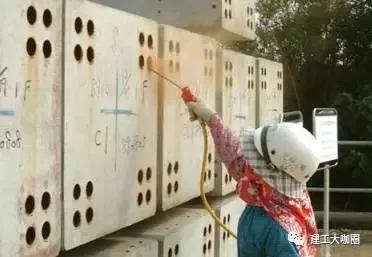
Figure 3-37: Cleaning the column sleeve
(2) Level the bottom elevation using shims: After positioning measurements are complete, measure the column bottom elevation. Based on the difference between the cast-in-place top elevation and design elevation, place shims at the bottom of the column. Use combinations of 10mm, 5mm, 3mm, and 2mm thick shims. Place shims approximately 0.25 times the column width at four points along the central sides. After adjusting verticality, secure all four footings of the column.
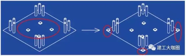
Figure 3-38: Shim installation sequence
During lifting and flipping of the column (prefabricated structure 3), protect the finished concrete at the bottom with yellow sand or rubber pads.
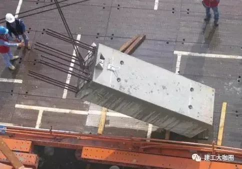
Figure 3-39: Lifting of prefabricated columns
(4) Once the column is initially positioned, temporarily fix it with diagonal bracing. According to detailed design drawings, install diagonal supports in both X and Y directions. The tower crane shackle should only be removed after these connections are securely locked.
(5) Lock the slant support fixing seats: After initial placement and temporary fixation with diagonal braces, install one slant support in each X and Y direction as per design drawings. Only after locking these connections can the tower crane shackle be removed.
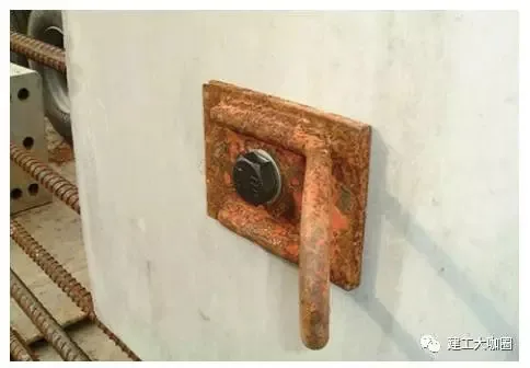
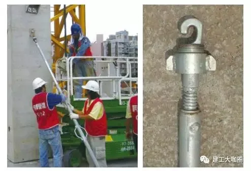
Figure 3-40: Locking of slant supports
(6) Measure verticality: Use a windproof vertical ruler to check deviation. Adjust the column’s verticality by manipulating the slant supports until it meets specification requirements. After adjustment, place shims at all four corners.

Figure 3-41: Measuring column verticality
7. Seal the bottom of the column with high-strength mortar to prevent leakage during grouting.
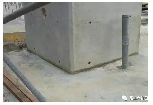
Figure 3-42: High-strength mortar sealing at column base
8. Sleeve grouting operation (for detailed sleeve grouting procedures, see Chapter 4).
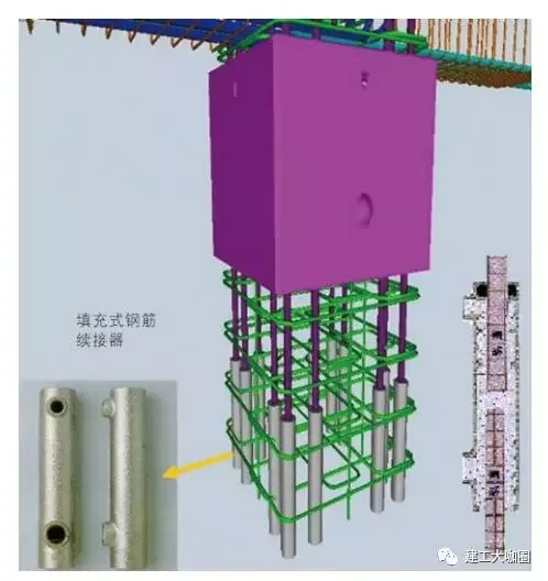

Figure 3-43: Simulation and on-site discharge of grouting material
3.7.2 Prefabricated Balcony and Air Conditioning Panel Lifting Operation
Before hoisting balcony panels and air conditioning panels, temporary support measures must be implemented. For balcony panels, the support system’s elevation should match the bottom elevation of the panel. The support on the balcony’s exterior side should be higher than the interior side by approximately 20mm to ensure proper positioning.
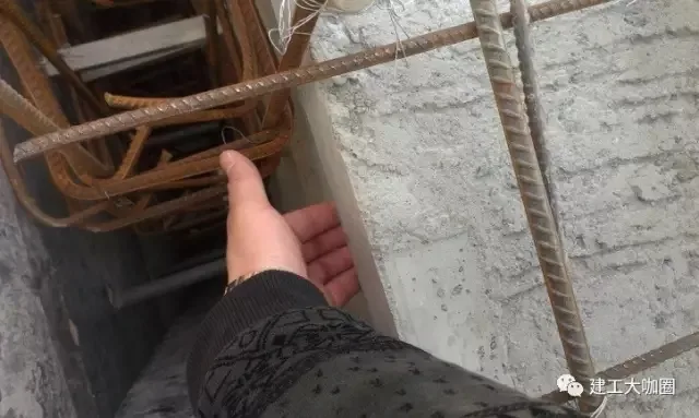
Figure 3-44: Balcony panel support system
Choosing lifting points should be done carefully, and their placement must be confirmed based on design specifications.
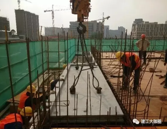
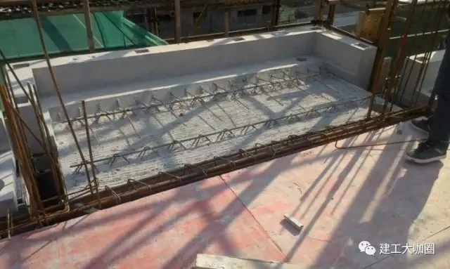
Figure 3-45: Hoisting and installation of prefabricated balcony panels
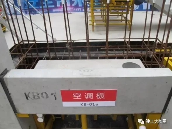
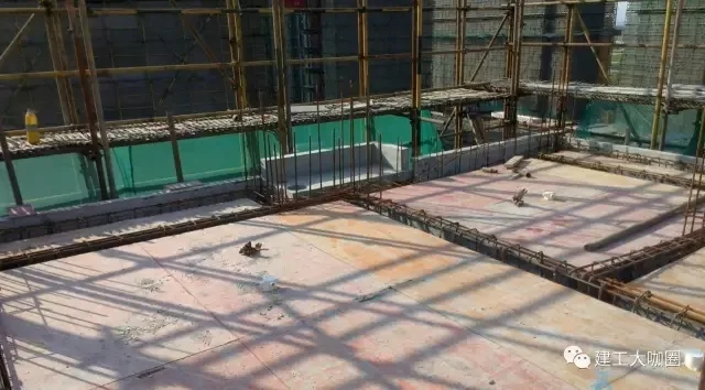
Figure 3-46: Installation of prefabricated air conditioning panels
Note: The copyright for the above materials belongs to Shanghai Jianfeng College and Shanghai Construction Second Construction Group.


Must log in before commenting!
Sign Up