Source: Construction Industry Celebrity Circle
Content Summary
The lifting operation of prefabricated concrete components plays a vital role in connecting and securing these components throughout the construction process of prefabricated buildings. It completes the assembly and connection of prefabricated concrete elements. This chapter provides a detailed explanation of the assembly operations for prefabricated concrete components, covering connection methods and characteristics of commonly used components.
It includes the assembly procedures for prefabricated concrete wall panels, floor slabs, beams, stairs, and other components. The chapter begins with an overview of universal connection processes and methods, followed by a comprehensive explanation of temporary connection techniques for various prefabricated components, steel bar connection nodes with cast-in-place structures, template selection, grouting operations, and related aspects.
4.1 Connection Methods and Characteristics of Commonly Used Precast Concrete Components
4.1.1 Assembly Process of Commonly Used Precast Concrete Components
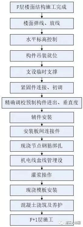
Figure 4-1: Assembly process of commonly used precast concrete components
(1) Construction Surveying and Setting Out: Using the construction drawings, floor lines are snapped and control lines marked 200mm outside the component lines, as illustrated in Figure 4-2.
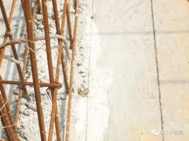
Figure 4-2: Construction surveying and setting out
(2) Horizontal Elevation Control: Before hoisting prefabricated components, bolts are adjusted to the required elevation using pre-embedded elevation adjustment devices and leveling instruments, as shown in Figure 4-3.
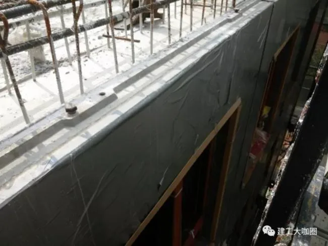
Figure 4-3: Horizontal elevation control
(3) Hoisting Prefabricated Components: The components are lifted and positioned into place, as depicted in Figure 4-4.
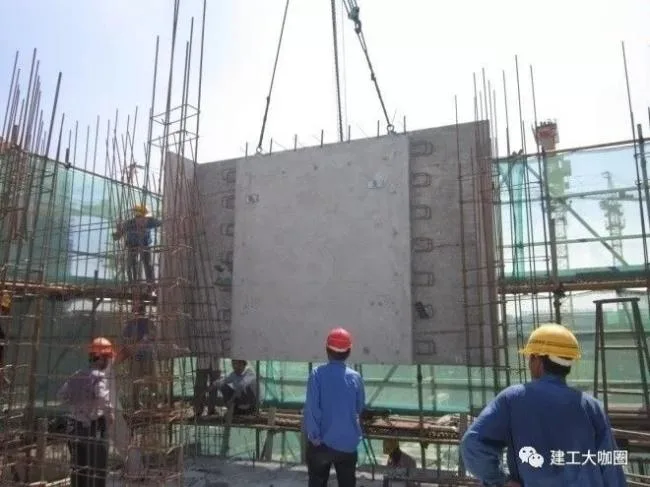
Figure 4-4: Lifting and positioning of prefabricated components
(4) Temporary Fixation: After placement, temporary supports are installed to secure the components, as shown in Figure 4-5.
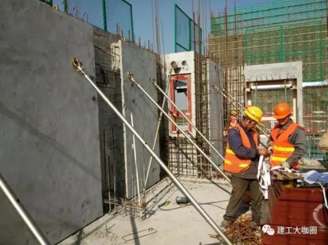
Figure 4-5: Installation of temporary support
(5) Fine Position Adjustment: The position of the prefabricated components is precisely adjusted using a precision adjustment device, as illustrated in Figure 4-6.

Figure 4-6: Precision adjustment of prefabricated component alignment
(6) Perpendicularity Adjustment: The vertical alignment of the components is fine-tuned using slant support devices, as shown in Figure 4-7.

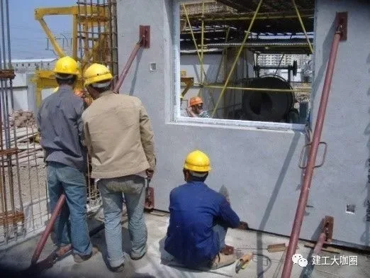
Figure 4-7: Inspection and adjustment of verticality for prefabricated components
(7) Sealing Joints: After precise adjustments, strong waterproof adhesive tapes are applied to the joints at the concrete pouring site to prevent leakage during pouring, as shown in Figure 4-8.
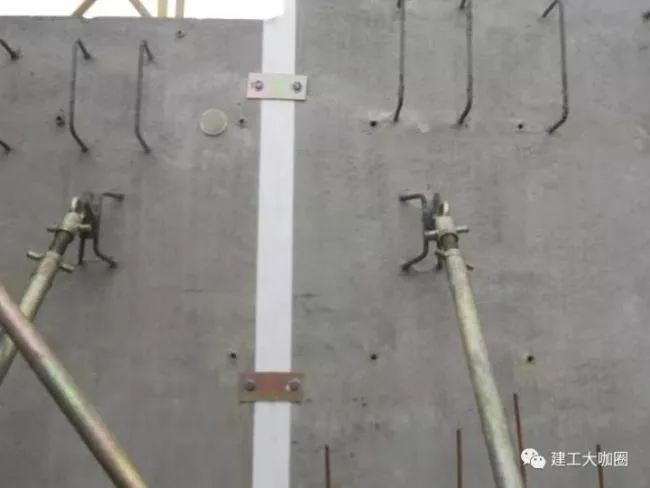
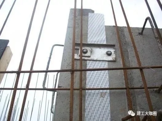
Figure 4-8: Installation of sealing accessories
(8) Reinforcement Binding: The reinforcement at cast-in-place connection nodes is tied securely, as shown in Figure 4-9.
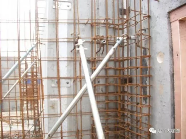
Figure 4-9: Reinforcement binding
(9) Formwork Installation, Concrete Pouring, and Curing: Both wooden and aluminum molds are assembled before concrete is poured, compacted, and cured, as shown in Figure 4-10.
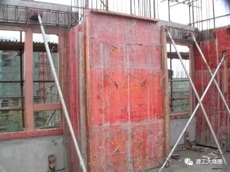
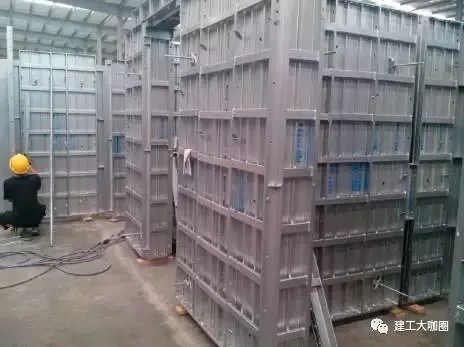
(a) Wooden mold assembly (b) Aluminum mold assembly
Figure 4-10: Template assembly


Must log in before commenting!
Sign Up