Revit is primarily used for Building Information Modeling (BIM). The Revit platform serves as a comprehensive design and documentation system, supporting all design, drawing, and scheduling needs for building projects. BIM enables you to access essential information regarding project design, scope, quantity, and phases.
Within Revit models, all drawings, 2D and 3D views, and schedules are visual representations derived from the same central building model database. When working in drawing or schedule views, Revit gathers and coordinates project information across every other project representation. The parametric modification engine in Revit automatically updates and synchronizes changes made anywhere—whether in model views, drawings, schedules, sections, or plans.
Most terminology used in Revit aligns with industry standards. However, some terms are unique to Revit itself. Understanding the concepts below is essential for using the software effectively.
Revit Project Configuration
In Revit, a project refers to a single database of design information, known as a Building Information Model. The project file contains all data related to the building design, including geometric forms and construction details. This encompasses the model’s design components, project views, and drawings. By utilizing a single project file, Revit allows you to easily modify designs and automatically applies those changes to all related views (plans, elevations, sections, schedules, etc.). Managing just one file simplifies project oversight.
Revit Elevation
Elevation in Revit refers to an infinite horizontal plane used as a reference for elements based on layers, such as roofs, floors, and ceilings. Elevation is primarily used to define vertical heights or building levels. You can create elevations for each known floor or other important reference points in the building, such as the second floor, top of a wall, or bottom of a foundation. Elevations must be placed within section or elevation views.
Revit Elements
When designing a project, parametric building elements can be incorporated. Revit organizes these elements by category, family, and type.
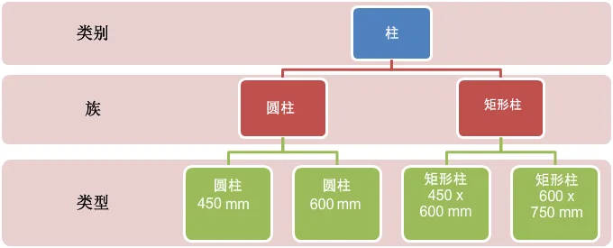
Revit Category
A category is a collection of elements used for modeling or documenting architectural design.
RevitFamily
A family is a group of elements within a specific category. Families organize elements based on shared parameters (attributes), similar functionality, and similar graphical representations. While the values of certain properties may differ among elements in a family, the property settings (names and meanings) remain consistent.
Structural families in Revit can be loaded into a project and created using family templates. You can specify attribute settings and graphical representation methods for these families.
System families in Revit cannot be loaded or created as standalone files. These families come with predefined property settings and graphical representations set by Revit.
Revit in-place families are used to define custom elements created directly within a project. If your design requires unique geometric shapes that you do not intend to reuse, or shapes that must maintain specific relationships with other project elements, in-place families should be created.
Due to their limitations, each in-place family contains only one type. You can create multiple in-place families within a project and place several copies of the same element. Unlike system and standard component families, you cannot generate multiple types by duplicating in-place family types.
Type
Each family can have multiple types. A type might represent a specific size, such as 30″ x 42″ or an A0 title bar, or a particular style, like the default alignment or angle style for dimensions.
Instance
Instances are actual items—individual elements—placed into a project. They have defined locations within the building (model instances) or within drawings (annotation instances).


Must log in before commenting!
Sign Up