Content source: Xiao Jiang said BIM

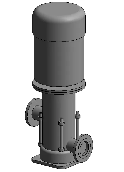
In electromechanical engineering modeling, equipment models are commonly used and are often referred to as “families.” How do we create models for typical electromechanical equipment such as water pumps and chillers? Here, we use the family template Metric General Model to design a fire booster pump.
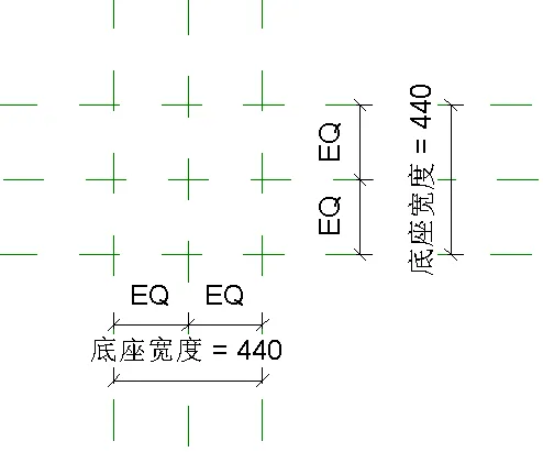
1. Creating the Base
Begin by drawing two horizontal and two vertical reference planes on the elevation reference plane. Use the DI annotation tool to evenly divide these planes. Assign a type parameter named “base width” for the width dimension.
Set the base length and width to 440mm by 440mm, and update the “base width” parameter accordingly.
Next, use the stretch command to define the base border. Apply a circular chamfer with a 60mm radius using the rounded arc tool to smooth the edges of the base.
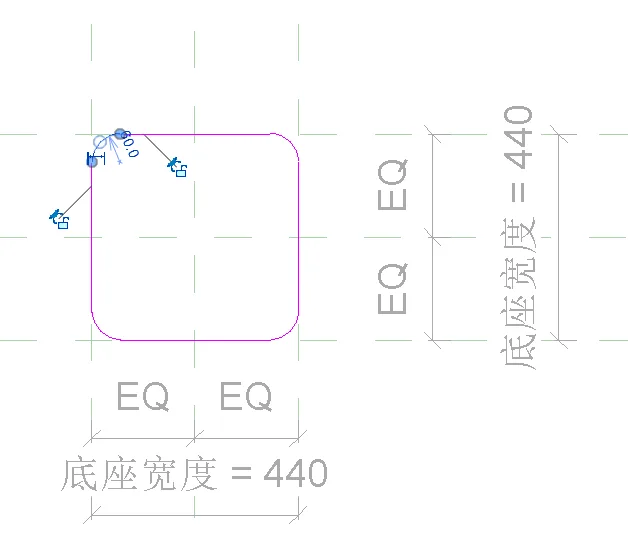
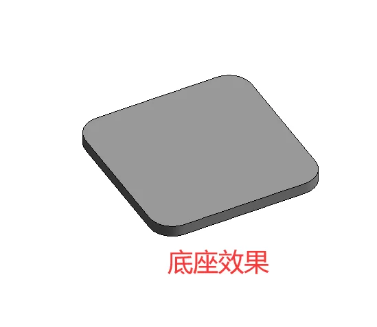
The base thickness is set to 30mm, using the stretch endpoint command to set the thickness accordingly.
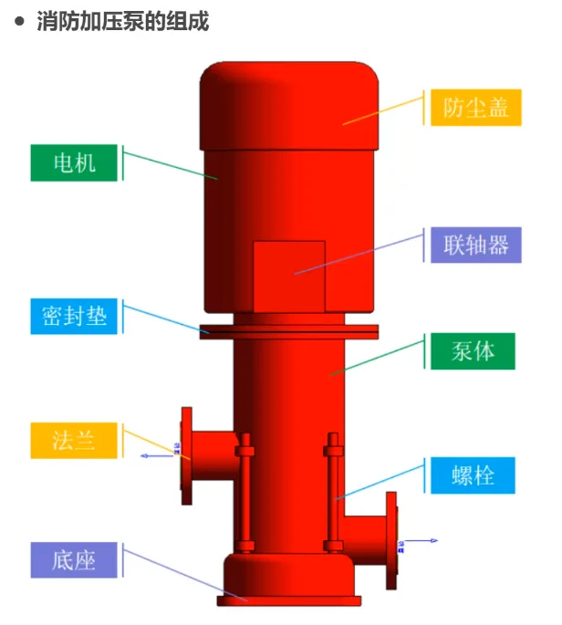
2. Modeling the Dust Cover, Motor, Gasket, and Pump Body
The water pump can be approximated as a cylindrical shape, so each component of the pump body is created using the revolve (rotation) command.
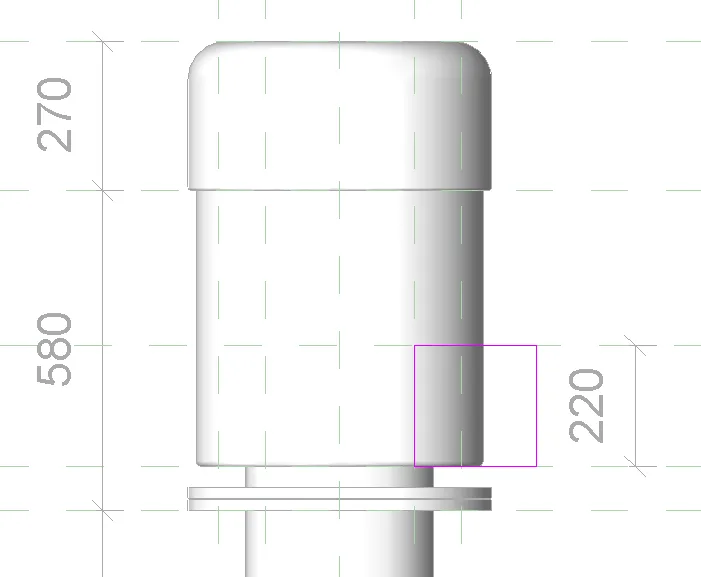
In the front elevation view, draw reference planes representing the height edges of the pump body, motor, and dust cover sequentially above the base. The heights from bottom to top are 130mm, 740mm, 500mm, and 270mm respectively. The corresponding horizontal cylinder radii are 200mm, 170mm, 260mm, and 275mm from bottom to top.
Use the revolve command to create these components by rotating the profile around the center vertical axis line.
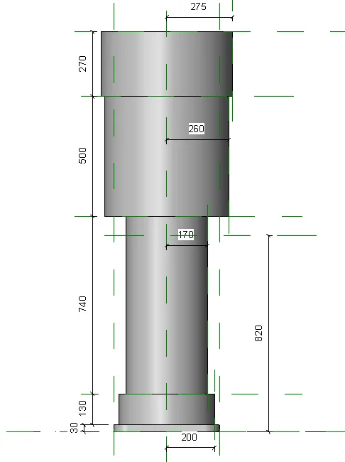
To add detail, the dust cover, motor, and base feature rounded chamfers, which can be added using the rounded arc tool within the revolving model.
3. Creating the Flange
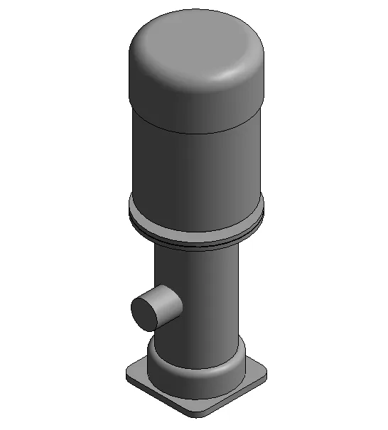
Start by drawing a connecting pipe:
- On the left facade, draw a reference plane at 460mm height from the bottom edge. Use the intersection of this plane with the vertical line as the center of a circle with a 75mm radius.
- Set the stretch endpoint to -300mm to define the length of the connecting pipe.
Next, still on the left facade, draw another circle with a radius of 150mm (note: the original text mentions 150mm75mm, which seems to be a typo; assuming 150mm), centered at 460mm height. Set the stretch endpoint to -330mm and the starting point to -300mm.
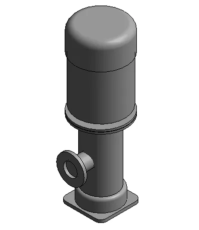
Then, add a sealing ring:
- Using the same center at 460mm height, draw a circle with a radius of 105mm.
- Set the stretch endpoint to -333mm and the starting point to -330mm, indicating the sealing ring thickness of 3mm.
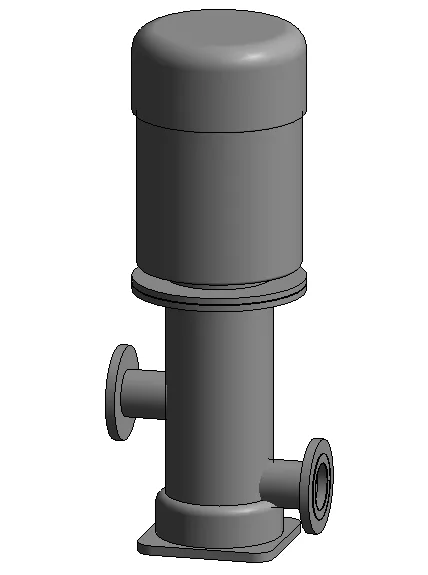
In the front elevation view, add a reference plane 200mm above the bottom; this is the center height for the second flange and connecting pipe. Select and mirror the previously drawn flanges and fittings, then move them down to align with the 200mm reference plane.
4. Creating Bolts
On the reference elevation plane, mark the intersection points for the four bolts. Use the stretch command to create bolts at these points.
The nuts are modeled similarly, with a thickness of 30mm.
5. Creating a Coupling
Draw a reference plane to define the vertical position of the coupling on the left facade. Use the stretch command to create the coupling with a start point at -110mm and an endpoint at 110mm.
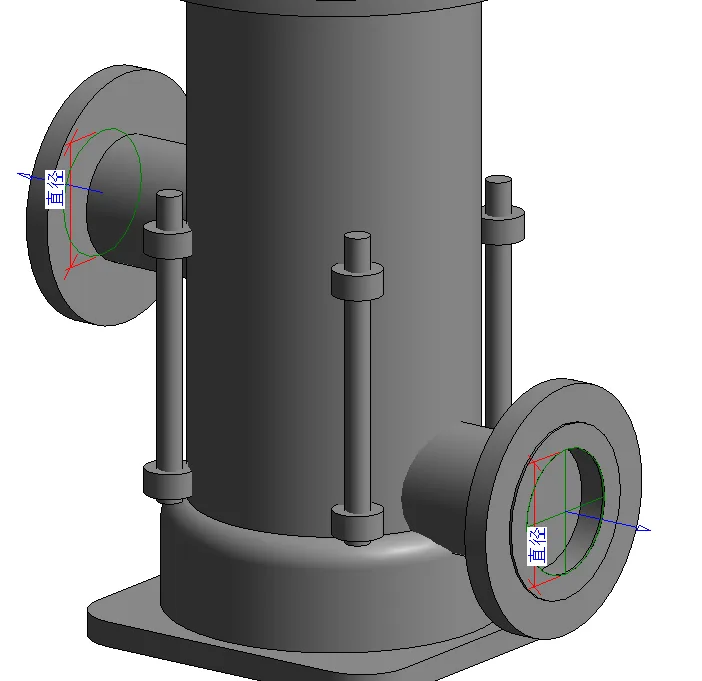
6. Adding Pipeline Connectors
Electromechanical equipment families require connectors to interface with external pipelines. In a 3D view, use the Pipe Connector tool to place connectors by selecting the edge ring of the sealing ring.
After placement, set the diameter of both connectors to 150mm.
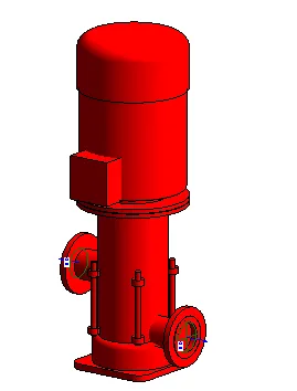
7. Applying Color Appearance
Select the water pump in 3D mode, open the material browser, create a new material, and set its color to red using RGB values (255, 0, 0). At this point, the family model of the fire booster pump is complete.


Must log in before commenting!
Sign Up