Content source: Xiao Jiang, BIM Expert

In subway equipment areas, pipelines require suspension using various types of hangers. When comprehensive support hangers are not used, screw rods combined with angle steel or channel steel hangers are applied. How can modeling methods determine the number of profiles needed to create hangers for subway engineering projects?
Let’s explore this by using the commonly applied screw hanger in air duct engineering as an example.
1. Selecting Materials for Hangers
For air duct installation and construction, hangers typically consist of screw rods paired with angle steel (or channel steel) crossbeams. The specific material specifications reference the “Rectangular Air Duct Lifting and Installation Material Table” found on page 76 of the 14ST201-2 “National Building Standard Design Atlas” (see Figure 1). Here, we model a hanger type with a 0.75mm duct wall thickness, insulation on the air duct, and an L63 * 4 angle steel crossbeam.
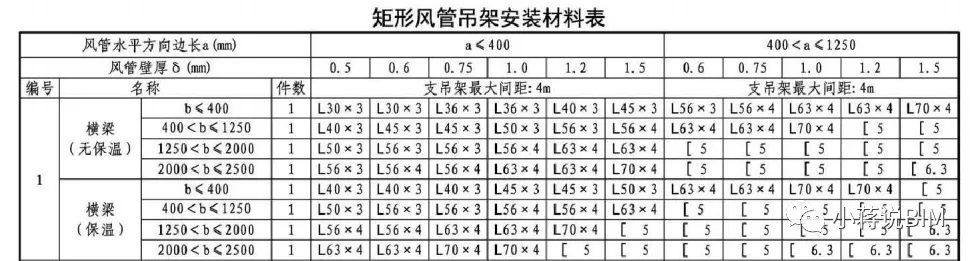
Figure 1
2. Creating the Hanger Family in Revit
(1) In Revit, create a new family using the “Metric Standard Model Based on Surface” template. This choice is based on the fact that hangers are typically anchored to the underside of structural floors, making this template more realistic than the standard “Metric Standard Model”.
(2) Define the hanger component directions: the “Reference Elevation” corresponds to the top view; the front elevation is the front view; and the rear elevation is the back view.
(3) Within the Front Elevation view, add various reference planes. To facilitate future dimension control with parameters, key faces of each component require reference planes, such as the crossbeam’s upper surface, its left and right ends, the centers of the left and right screws, and the air duct’s left and right ends.
According to the air duct hanger installation atlas, the distance from the air duct edge to the screw rod is 150mm, while the distance from the beam edge to the screw rod is 50mm (see Figure 2). Additionally, the screw rod extends 50mm below the beam’s top surface. These dimensions are managed using alignment dimension annotations.
Create hanger parameters to control these dimensions: an instance parameter for the distance from the beam surface to the top plate, and another instance parameter for the duct width (see Figure 3).
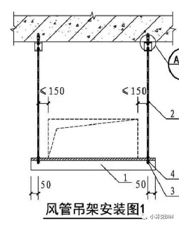
Figure 2
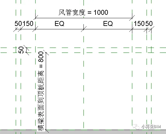
Figure 3: Front elevation with parameter settings
(4) Modeling the hanger components:
Beam: Using the stretch command in the right elevation view, create the cross-section of the L63 angle steel beam. Lock the bottom edge of the cross-section to the reference plane representing the “beam upper surface” (see Figure 4). Return to the front elevation, select the shape control handles, drag the two ends of the angle steel to the “left and right end faces of the crossbeam” reference planes, and lock them. Alternatively, adjust the “stretching start point” and “stretching end point” in the properties bar to “700, -700” and lock to the reference planes.
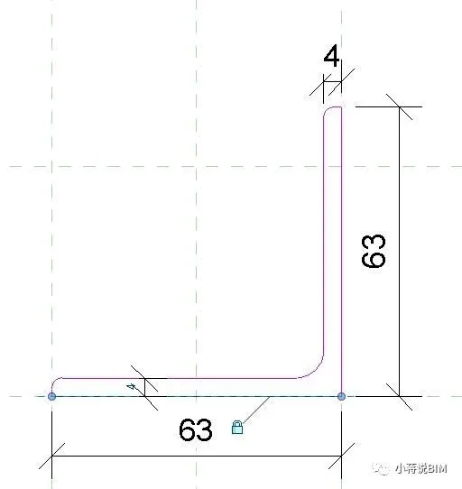
Figure 4
Screw Rod: The screw rod is a Φ8 screw rod. On the reference plane layer, use the stretch command to draw a circle with a 4mm radius at the intersection of the left and right center reference planes of the screw. Drag the shape handle to the slab’s top reference plane and lock it (see Figure 5).
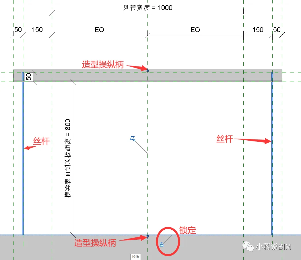
Figure 5: Screw rod locked in position
Nut: Draw reference planes for the nut’s top and bottom surfaces in the front elevation. Note the distance between these surfaces and the beam’s upper surface. Use the “outer polygon” tool in the floor plan view to shape the nut at the corresponding location. Mark the distance from the reference plane line where the nut center is located to one boundary point of the regular hexagon (see Figure 6). Then drag the nut’s upper and lower handles to the “Top and Bottom Reference Plane Lines” and lock them in the front elevation view (see Figure 7).
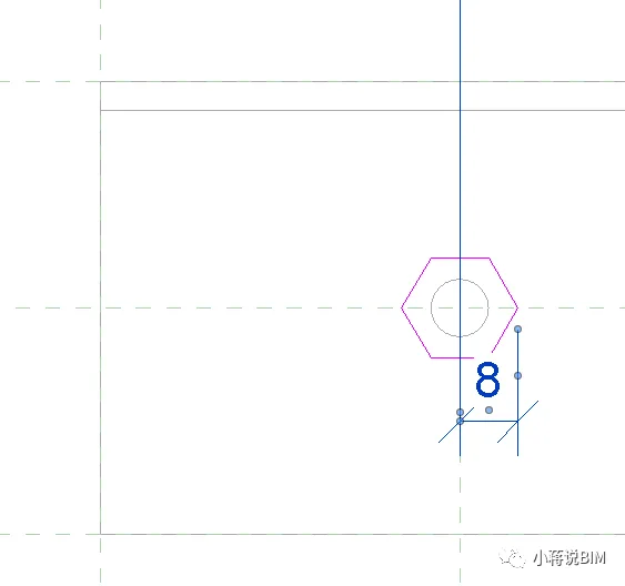
Figure 6: Nut plan view
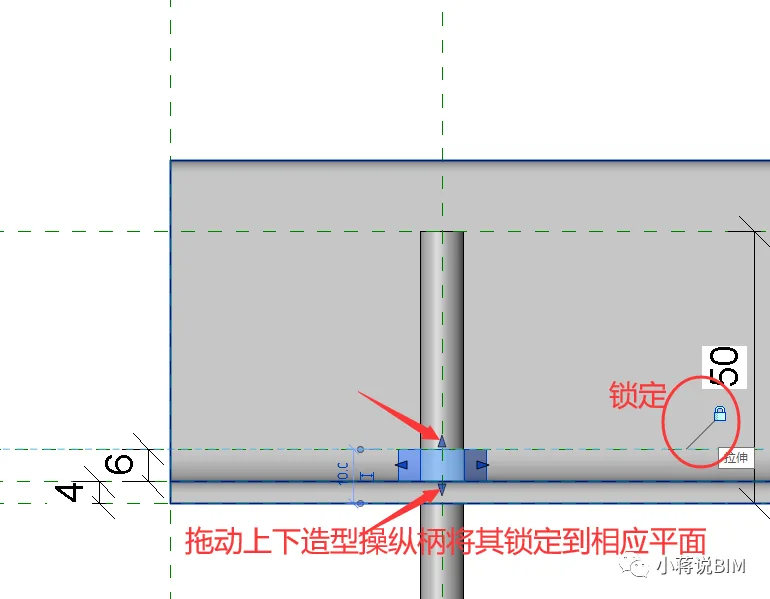
Figure 7: Nut elevation with locked heights
(5) Parameter refinement and validation:
To accurately calculate hanger materials in project schedules, create shared parameters such as “Length of Cross Arm Angle Steel” and “Total Length of Hanger Screw”. Assign calculation formulas to these parameters to enable precise length measurement of hanger components (see Figure 8).
After completing the family creation, adjust the parameters to verify correct hanger behavior and prevent errors like disassembly or distortion.
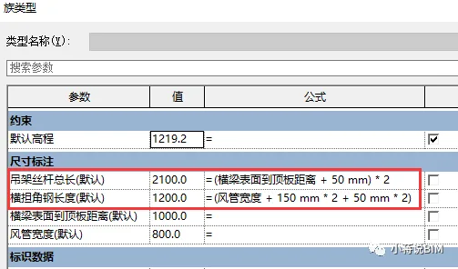
Figure 8: Formula assignment for parameters
3. Applying the Hanger Family in Projects
Load the hanger family into a test project, adding screw hangers (each 3 meters long) to two air ducts. Then, tally the quantity of screw rods and angle steel materials used, as shown in Figures 9 and 10.
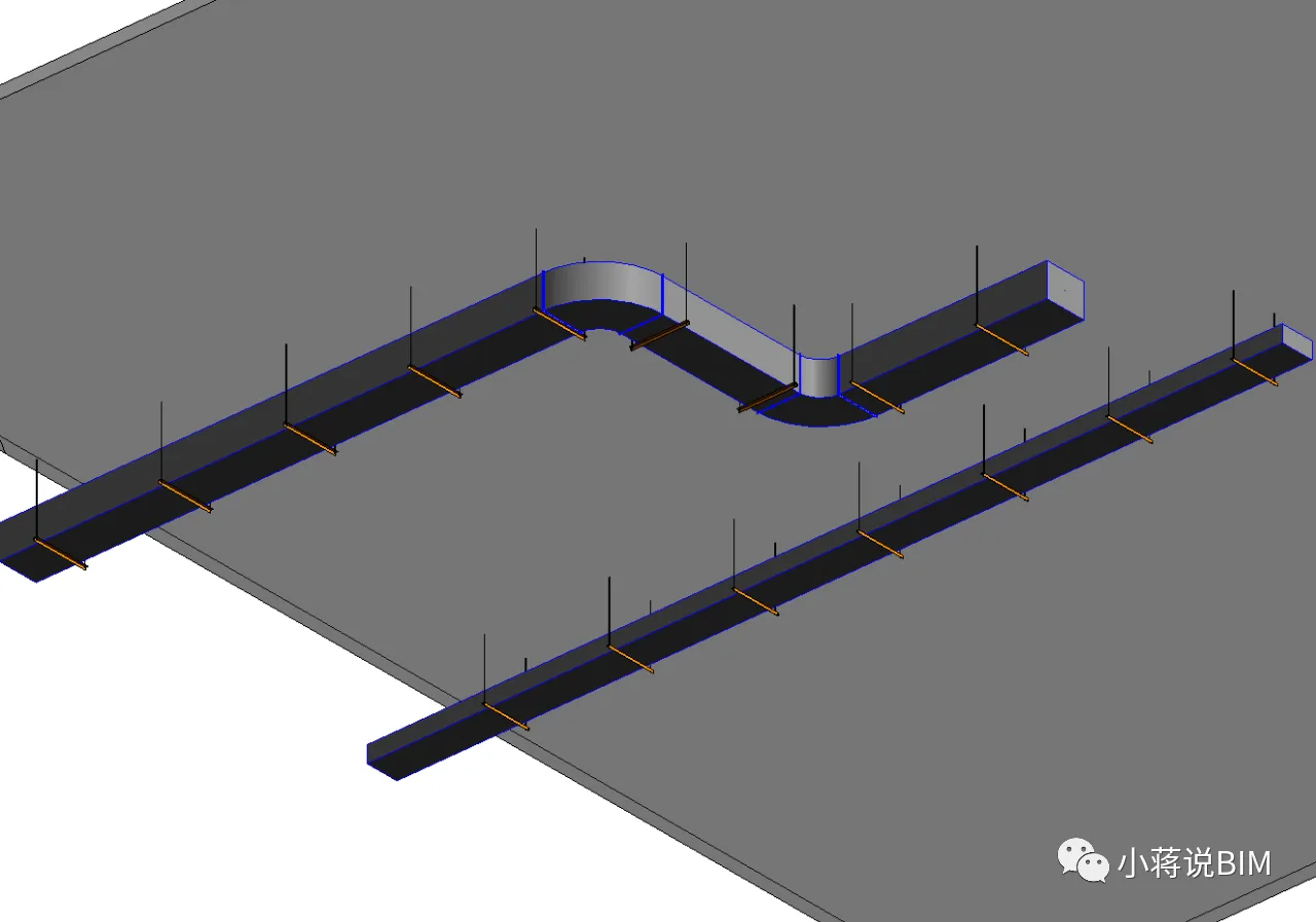
Figure 9
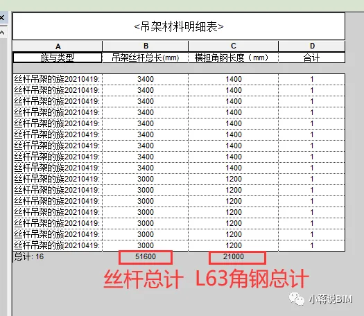
Figure 10: Total quantity of hanger materials
Summary
This experiment demonstrates that hanger material quantities can be accurately calculated within a project using family modeling in Revit. For different hanger designs—such as hangers with both vertical and horizontal angle steel beams or those made entirely of channel steel—it is essential to build corresponding families and integrate them based on actual project requirements.


Must log in before commenting!
Sign Up