Within the Revit Management tab (ManageTab) under the Settings panel (Setting), you can find the line width configuration option in the Additional Settings section. This interface allows you to customize line widths for model lines, perspective view lines, and annotation lines.
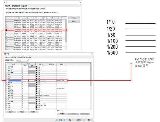
Figure 3.24: Definition of Line Width Unit Value and Unit Quantity
As illustrated in Figure 3.24, the line widths for all model lines in Revit are not fixed values; instead, they adjust dynamically based on the scale. For example, the wall section line assigned a line width value of 5 is shown with varying widths of 1mm, 0.7mm, 0.5mm, 0.35mm, and 0.25mm across scales from 1:10 to 1:500. The legend clearly shows that line widths decrease proportionally as the drawing scale shrinks.
This behavior means that when exporting Revit models to PDFs, the final drawings may appear differently depending on the scale used. Unlike CAD, this approach reflects Revit’s model management and output methodology. Since a wall component in Revit may appear in outputs ranging from 1:20 to 1:500, it is challenging to assign a single line width value that suits all scales.
Using the bathroom floor plan in Figure 3.25 as an example, we can further understand the importance of Revit’s line width control system. The wall section line is set to a line width value of 5 in the object style. Comparing different scale drawings demonstrates how line widths vary: at 1:10, the wall line width is 1mm, while at 1:20 and 1:50, it reduces to 0.7mm.
However, this proportional adjustment impacts the representation of wall decorative layers. If a uniform line width, such as 1mm, were applied across all scales, this issue would be even more pronounced. Fortunately, the 1:20 and 1:50 drawings typically do not require detailed wall structure representation, and Revit offers settings to manage the relationship between scale and drawing detail complexity, as shown in Figure 3.26. This example clearly highlights the rationale behind Revit’s line width settings.
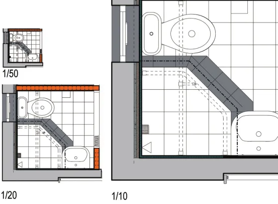
Figure 3.25: Example of Line Width Settings at Different Scales
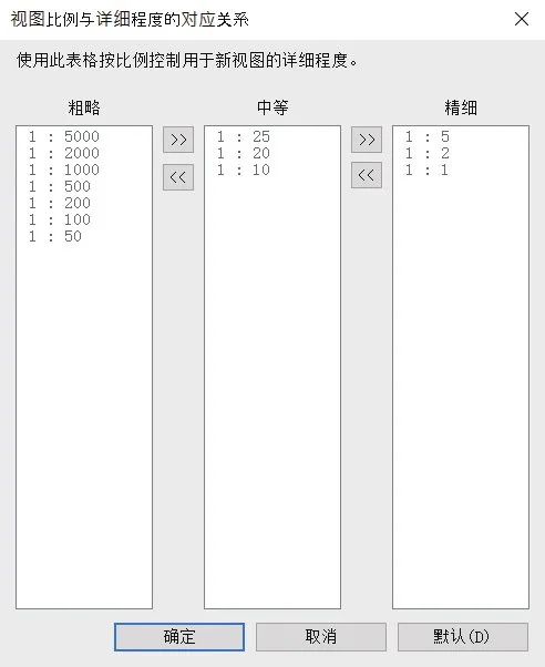
Figure 3.26: Relationship Between View Scale and Detail Level
The line width table can be further customized to suit specific project requirements, as demonstrated in Figure 3.27. For instance, adjusting the line width value of 5 at a 1:20 scale to 0.18 significantly improves the drawing’s clarity, allowing distinct display of the decorative and insulation layers. This adjustment will consistently appear in subsequent PDF exports.
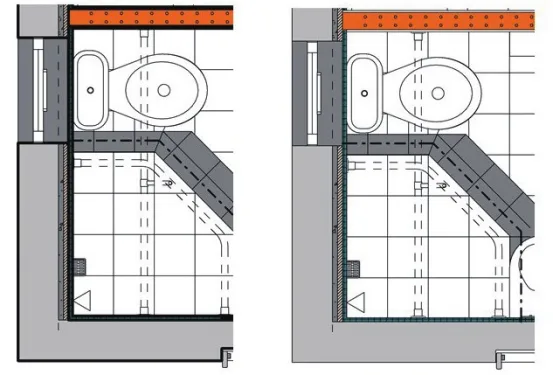
Figure 3.27: Comparison of Surface Effects with Adjusted Line Widths
—Excerpt from “BIM Design Software and Drawing – Drawing Practice Based on Revit” by Li Yiyi
For learning and exchange purposes only. Copyright belongs to the original author and publisher.


Must log in before commenting!
Sign Up