This article is from the WeChat official account: Wuqibazao’s shop.
In Revit, the primary method for alignment is using either the project base point or the origin point.
Advantages: This approach is simple, easy to understand, and requires minimal effort. It generally ensures that models export correctly across all platforms and formats without offset issues.
Disadvantages: It is not ideal for design changes or model reuse, especially when there are height differences. Manual conversions are necessary, which significantly increase the chance of errors.
Before discussing project shared coordinates, it’s important to understand the concepts of North and True North. Due to varying land conditions, not every project is perfectly aligned with geographic south or north. Therefore, project orientation is considered in the planning diagrams, where the “north” refers to true north or geographic north.
When producing detailed plans, buildings are generally drawn in their standard orientation. Once the drawing is complete, a compass is added to the first floor to clearly indicate the angle. In simple terms, Project North is used to simplify drawings and define orientation.
Measurement Point: This represents a known, fixed point in the real world.
Project Coordinates:
In planning diagrams, the XY coordinates of the red line corner points are usually specified. The designer determines the exact placement within this boundary. After confirmation, coordinates of critical points, such as wall corners, are marked. Additionally, a special point (often A=B=0 or A=B=100) is defined as a reference. The placement of other buildings within the site is based on this benchmark point.
Simply put, for a single building, it is feasible for all RVT projects to share a project baseline. However, for substations or complex sites, zoning drawings may be preferable for performance and efficiency. Multiple buildings can be modeled individually and then assembled later.
To facilitate this, each RVT file can be treated as a standalone project. Each project has its own independent project base point, with the default zero elevation corresponding to indoor ±0.00 elevation. Based on this, specific models are created and coordinated. Positioning between multiple projects is then managed through defined relationships.
Assuming we define a reference point file in advance—with an origin, project base point, measurement point unchanged, and rotation angle set to zero—and knowing its exact latitude, longitude, and elevation, all other files can be positioned and adjusted relative to this point. Adjustments may include translation, rotation, and even mirroring, ensuring the plans align correctly. This relative relationship can be shared across models.
There are two ways to achieve this in Revit:
- Link all files into the overall plan (the reference point file) and adjust their positions within this central file.
- Predefine benchmark files. After individual models are created, link the reference point file to adjust relative positioning.
Overall, the first method involves less work but is less suitable for version management. Therefore, this article focuses on the second approach.
Here is the general workflow, using an outdoor power plant as an example:
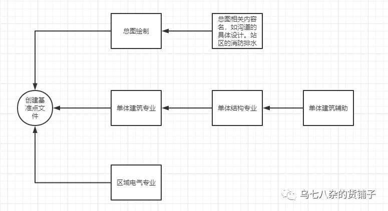
First, create a benchmark file. Then, work on the overall plan, individual buildings, or area electrical models. Once this is done, link the reference point file. By moving the reference point, you establish relative constraints. This synchronization is done via Manage > Coordinates > Acquire Coordinates.
After completing individual units, other drawings can be created based on this framework. The key is to ensure that the final workflow synchronizes with the baseline file’s coordinates. Typically, coordinate synchronization is done after the first drawing is complete, followed by archiving the design file. Other files can be linked through intermediate files for coordinate transmission—for example, linking the Building Model to the Benchmark File, then linking the Structural Model to the Building File. This process is transferable and scalable.
It is important to note that exporting IFC files in Revit 2018 only supports selecting reference points during export. By default, it exports measurement points, which can cause misalignment or incorrect rotation in some projects. Revit 2020 improved this by localizing and supporting IFC export options. Therefore, this article mainly focuses on Revit 2020 operations. For version 2018, manual adjustments are required (not recommended), and it is important to check compatibility with the receiving platform, as some platforms do not support relative position adjustments of Revit models.
Regarding coordinates, elevations, and angles in GIS: coordinates adjust the model reference points, while elevation and angle act as correction values applied under specific conditions. For example, if a project has a northerly rotation of 30 degrees and an elevation of 45 meters, and these conditions are accounted for when using shared coordinates, no further corrections are needed. This section covers the practical application of relative (shared) coordinates.


Must log in before commenting!
Sign Up