This article is sourced from the WeChat official account: Xiangge BIM Lecture Hall.

Those experienced with Revit understand that its capabilities for steel structure modeling are quite limited. In contrast, Tekla has a long-established reputation and robust software for steel structure modeling. Many steel manufacturers rely on Tekla for modeling, drawing, and cutting tasks. Thus, when working on steel structure engineering projects, Revit still plays a role, which raises the question of how to achieve smooth import and collaboration between the two software.
Many colleagues often ask:
1. How to import Revit models into Tekla;
2. How to coordinate Tekla with Revit after importing, or how to align the position of Tekla models with other professional models in Revit.
Let’s start by clarifying the fundamentals of graphics origins and coordinate systems.
First, we need to introduce two key concepts: the origin point in Revit and the origin point in Tekla.
Revit’s origin, as explained previously by Brother Xiang, corresponds to the same point as the CAD origin (X=0, Y=0). If you are unfamiliar with this, I recommend reviewing Brother Xiang’s course on the Revit Origin.
Similarly, Tekla’s origin is a coordinate point at (X=0, Y=0, Z=0). Below, I provide a detailed explanation of Tekla’s coordinate origin using images and descriptions.
1. Double-click the Tekla axis to open the “Axis dialog box.”
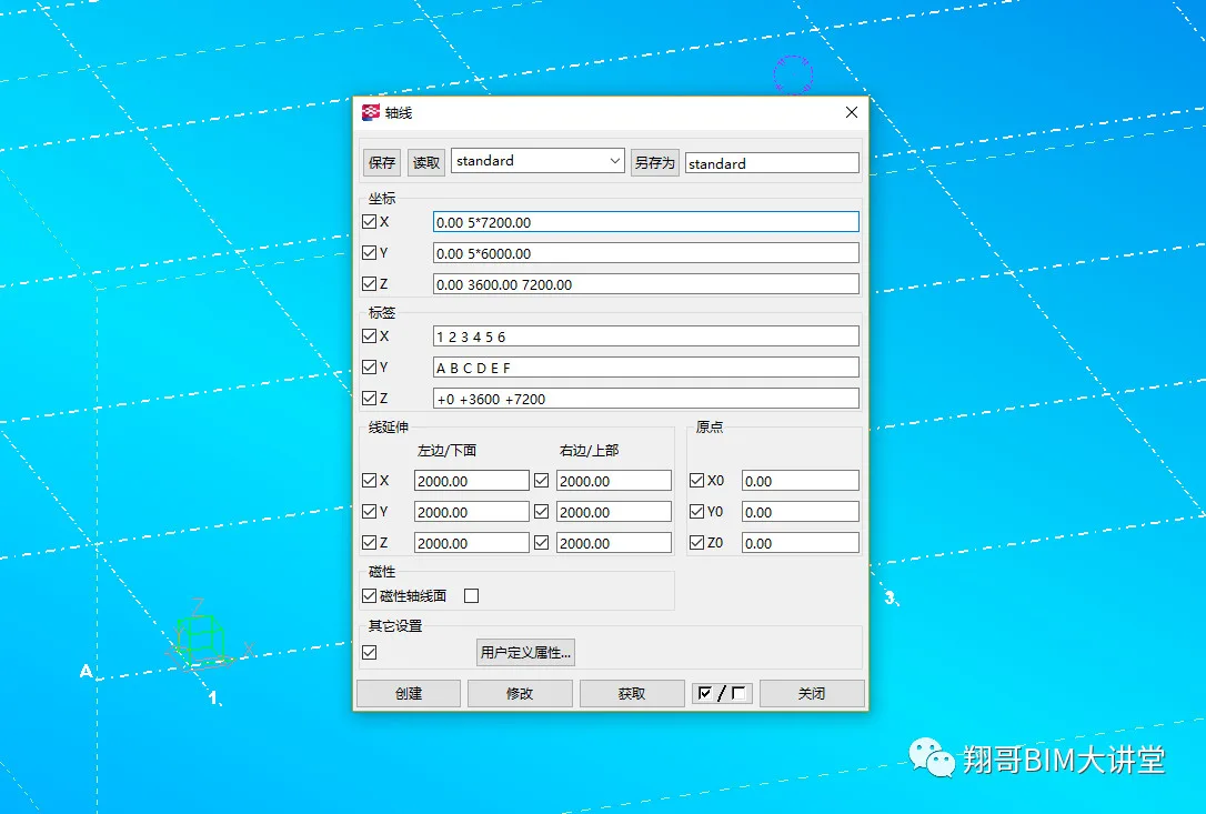
2. Set the starting point coordinates (X, Y, Z) of the axis to zero.
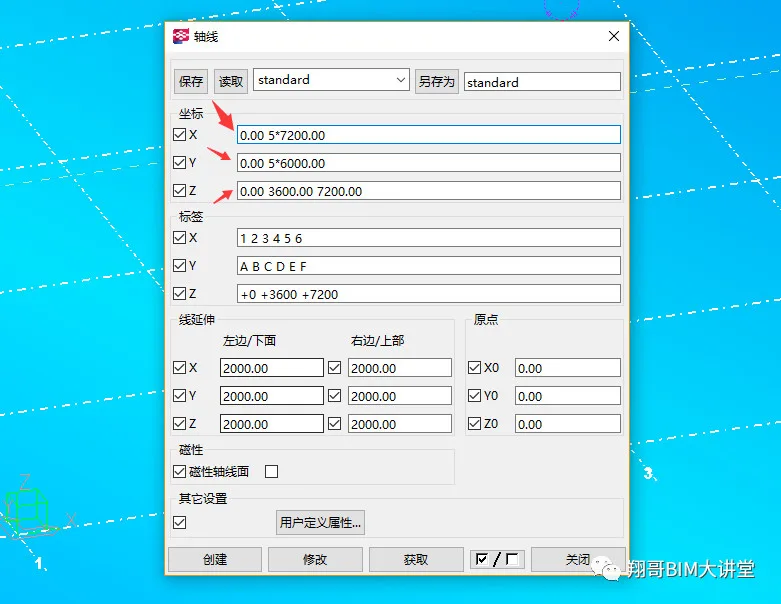
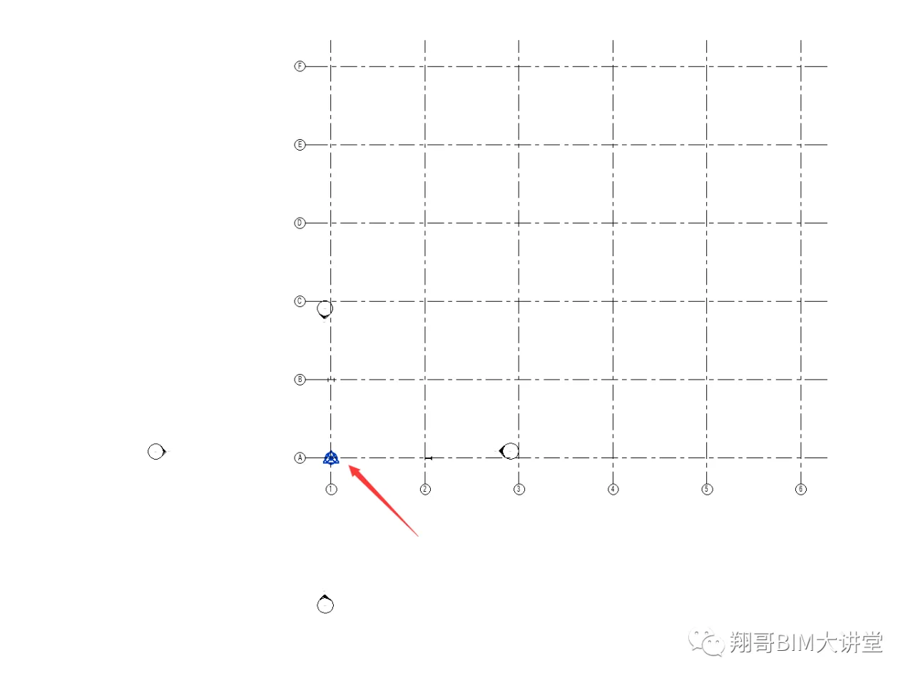
3. By doing this, we unify Tekla’s coordinate origin with the point (X=0, Y=0, Z=0), which matches Revit’s origin, as shown below.
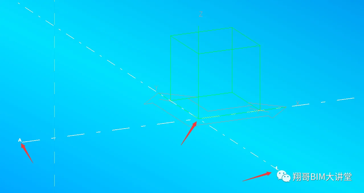
The image illustrates that Tekla’s coordinate origin is at the intersection of the starting axis 1 and the A axis, representing the point (X=0, Y=0, Z=0). After unifying the origins, the coordinate systems of Revit and Tekla are aligned.
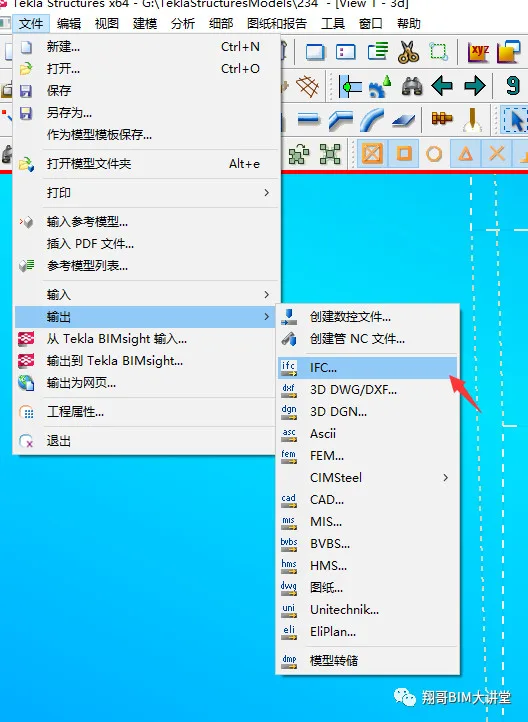
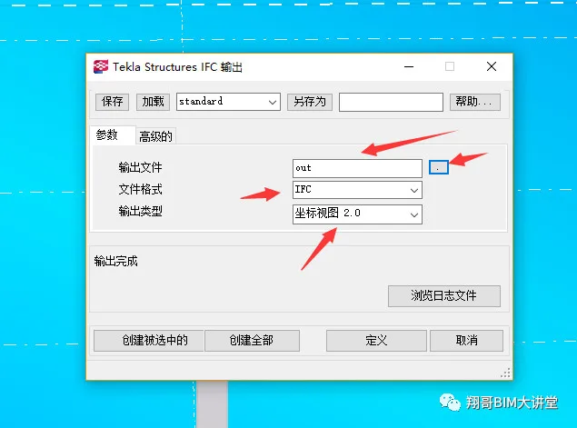
4. Once the coordinate systems are unified, build your steel structure model in Tekla accordingly. After modeling, export the model in IFC format (see image). Note: Before exporting, make sure to explode the nodes in the model to avoid construction losses. To export, go to “File” → “Output” → “IFC”.
5. In the output dialog, set “OUT” as the path to save the exported file. Choose the file format as IFC.
For output type, select “Coordinate Attempting 2.0.”
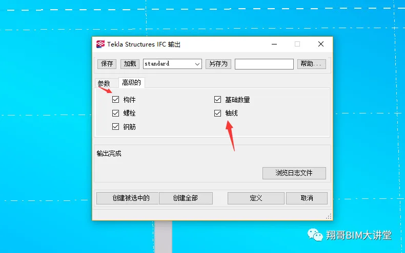
6. In the advanced settings, check all options. Note: Checking axis lines and linking them to Revit facilitates positioning. However, overlapping axis lines cannot be deleted in Revit, so it is generally not recommended to check this. For tutorial purposes, this option is enabled here.
7. Click “Create All” to import the exported IFC file into Revit.
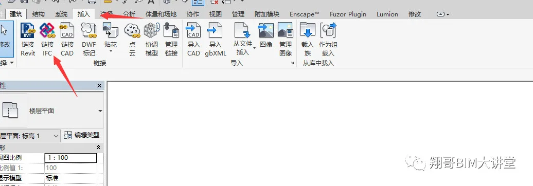
8. When linking the IFC file into Revit, the software automatically aligns Tekla’s origin with Revit’s origin.


Must log in before commenting!
Sign Up