This article is from the WeChat official account: Hongjian Smart Building. When creating models, clients often request an exploded view of a specific node, showing the individual components clearly separated. How can this be achieved in Revit?
01 Model Creation
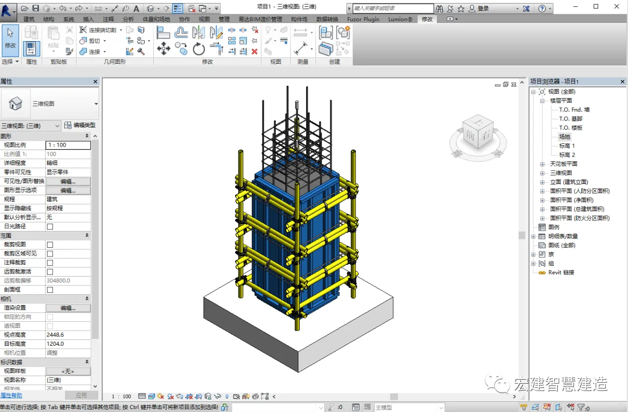
First, based on the client’s requirements and CAD drawings, we create the node in Revit. In this example, the editor uses the frame column process to illustrate the steps.
02 Replacing Graphic Elements
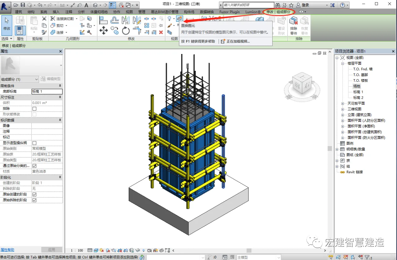
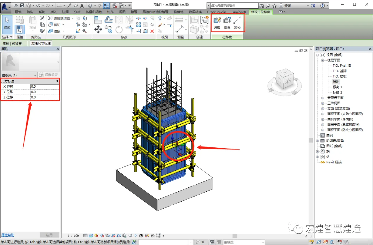
Select the component you want to explode. If it’s a standalone part, go to the Modify tab in the menu bar and click on the replacement element option. A Cartesian coordinate system will appear on the component, allowing you to move it freely. You can adjust the position manually, enter precise numerical values on the left panel, or define a path for the movement before relocating the component.
03 Creating the Explosion Model
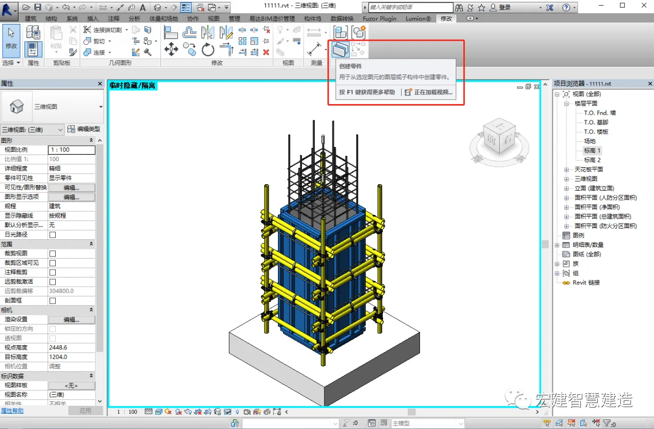
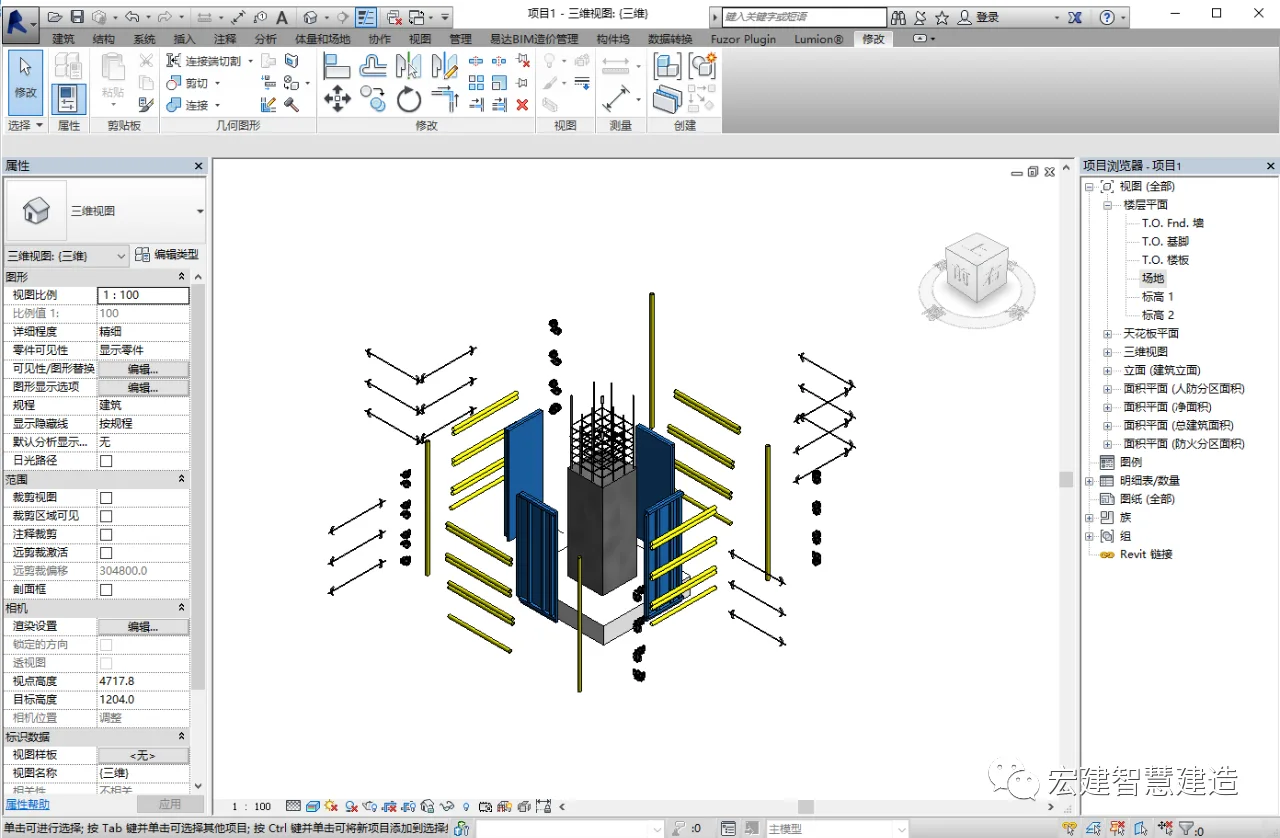
If the components to be exploded belong to a complete family, you first need to break it down into individual parts—essentially disassembling the model. Then, select each part separately and use the replacement element tool to move them apart. Repeat this for all components until the exploded model is complete, allowing you to clearly observe the structure, spatial relationships, and individual elements.
04 Rendering the Explosion Diagram
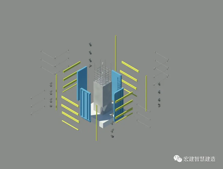
Finally, adjust the viewing angles according to the client’s specifications and render the exploded model image for presentation.
Source | BIM Consulting Department (Huang Bin)
Layout | Engineering Information Department
Editor in Chief | Stone Sponge Double
Review | Cao Liansha


Must log in before commenting!
Sign Up