Question: How can you locate the contour of a pipeline when determining its size in a pipeline profile?
When positioning pipeline dimensions in a comprehensive cross-sectional view, measurements typically focus on the pipeline’s centerline. While this method accurately defines the pipeline’s position, it can be inconvenient during actual design and construction. Specifically, understanding the spacing between pipelines or the distance from pipelines to walls is difficult using centerline measurements alone. These distances must be inferred by referencing pipeline sizes and performing calculations, which is cumbersome.
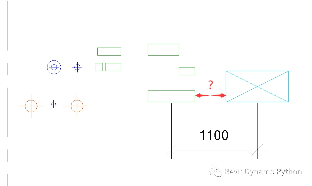
So, is it possible to annotate the actual outline of a pipeline in Revit? The answer is yes.
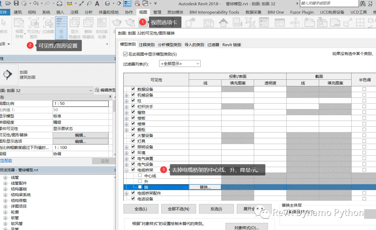
To label the pipeline boundaries, you need to adjust the elevation and visibility settings. In the view’s Visibility/Graphics Overrides (VV or VG), turn off the display of the centerline and the elevation indicators for cable trays and ducts.
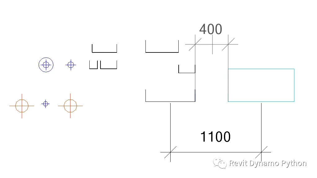
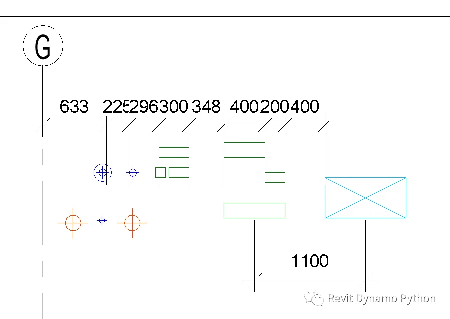
Once the centerline and elevation symbols are hidden, you’ll notice that the alignment annotations now capture the true outline of the pipeline.
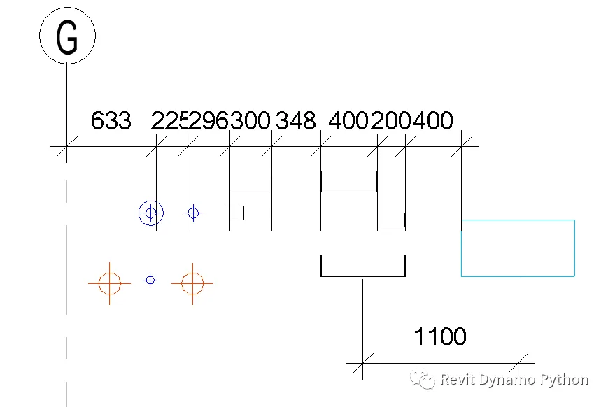
This same approach applies equally to water pipes.
At this point, although the standards are followed, the display style may not meet drawing requirements. This often requires switching between two sets of view templates: one for design, using styles that allow annotations, and another for drafting, applying comprehensive pipeline section templates. However, this workflow may now be considered outdated.


Must log in before commenting!
Sign Up