Creating a project in Revit begins with selecting the right project template. The choice of template significantly influences the project’s initial setup, directly impacting the efficiency and accuracy of model construction. A well-designed template can dramatically improve productivity, essentially achieving twice the results with half the effort. Therefore, the first step is to select a project template that complies with China’s building standards and is comprehensive enough to minimize adjustments during the modeling process, thereby enhancing design speed.
Design work is carried out within the template file, where various components are placed and parameter information is added to build the model and complete the project. Template files use the “.rte” extension, while project files use “.rvt”. Revit includes built-in project templates, but designers can also create custom templates tailored to their specific projects. These templates establish initial parameters such as default measurement units, elevation baselines, grid configurations, imported families, and material browser settings.
Mastery of Revit’s modeling tools is essential for building accurate models. The most commonly used tools are outlined below:
1) Tab Tools
Starting with Revit 2013, the software integrates architectural, structural, and MEP (mechanical, electrical, plumbing) modeling tools into a single platform. This integration allows users to design architecture, structure, plumbing, and electrical systems all within one interface. Most of the modeling tools for different disciplines are located within the tabbed interface.
The tabs cover a wide area of the Revit interface and include the Architectural, Structural, Systems, Insert, View, Modify tabs, among others. Each tab provides tools specific to its function. For example, the Architectural tab contains tools related to architectural modeling. Users can switch between tabs with a simple left-click, facilitating quick and intuitive operations.
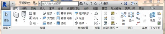
Figure 1: The Revit Architecture Tab
A special tab called the Modify tab plays a crucial role during model construction, as editing and modifying elements is often necessary to meet design requirements. When no element is selected, the Modify tab appears in a light gray color, similar to other tabs. However, once an element is selected, the Modify tab highlights in light green, indicating its active status. This tab contains various editing commands such as Move, Copy, Trim, Mirror, Rotate, and Split, which are essential for element modification.
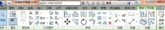
Figure 2: The Revit Modify Tab
2) Properties and Project Browser Panels
Aside from the tabs, two essential panels in Revit are the Properties panel and the Project Browser panel. These panels usually appear on the left side of the interface when a project file is opened. They can also be rearranged according to user preferences.
The Properties panel displays information about the currently selected object. If no object is selected, it shows details about the current view. This panel contains comprehensive data about each component, reflecting the core concept of Building Information Modeling (BIM). The first section in the Properties panel is the Type Selector, which allows users to choose the family type from a dropdown menu. For instance, when working with walls, you can select different wall types here.
Below the Type Selector, users can edit attributes such as geometric dimensions, materials, functional properties, and thermophysical characteristics. Further down, information regarding the component’s location, connections, and dimension annotations is displayed. This panel is fundamental to distinguishing Revit from traditional design software and is key to implementing BIM technology.
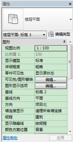
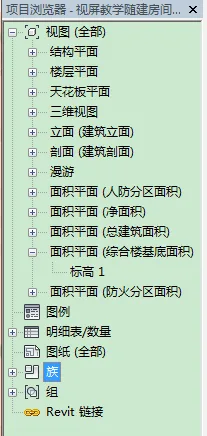
Figure 3: Properties Panel Figure 4: Project Browser Panel
The Project Browser panel organizes views, schedules/quantities, and families. Managing views is a fundamental operation in Revit, as views represent different projections or sections of the model from various angles. Common views used in HVAC design include floor plans, elevations, and sections, as illustrated in Figure 4.
The schedules and quantities tool generates statistical data from the model in chart form, such as room schedules, usable area schedules, drawing lists, and material takeoffs. If the model is accurately built, detailed quantity takeoffs can be automatically produced upon completion. These quantities are crucial for developers, contractors, material suppliers, and for bidding and tendering processes.
The Families section contains system-built family types as well as custom families that designers can load or create. Families can also be edited or modified within this panel.


Must log in before commenting!
Sign Up