Article source: Installation Engineering Technology Sharing Platform
Tekla Modeling – Drawing Method
- Create axis lines.
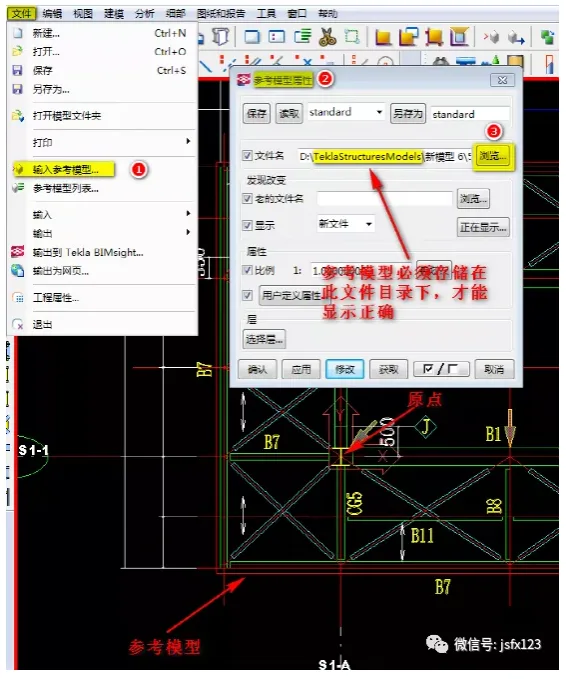
- Input the reference model:
Select the required drawing as a reference model in CAD. Remove any irrelevant data, then copy the cleaned drawing to a new file. Move this drawing to the origin position and save it under the target model.
In TEKLA, enter the reference model, select the reference model file name, and choose the origin as the insertion point.
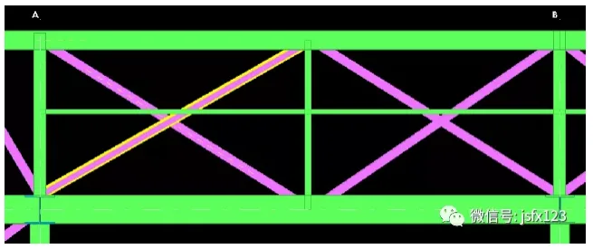
- Create part drawings based on the reference model:
Use modeling commands according to the parts required on the reference model to generate detailed drawings of the components.
- Common issues when importing reference models:
- Reference model not displayed:
Check View Properties > Display > ensure Reference Object is enabled.
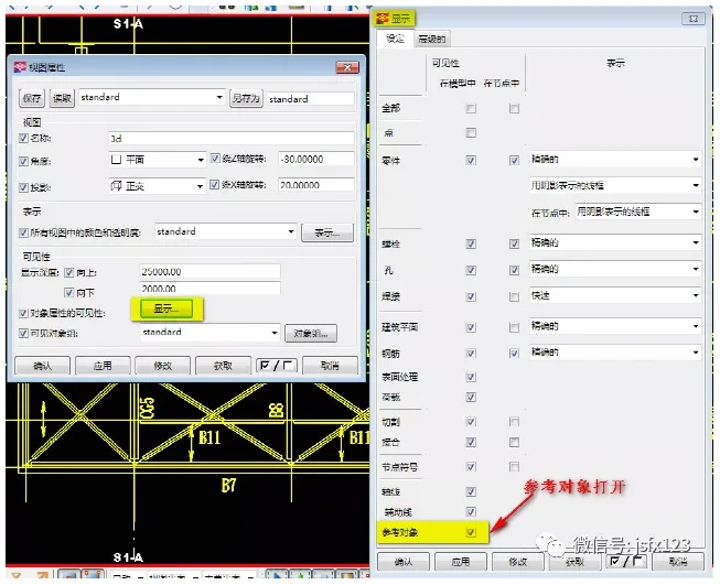
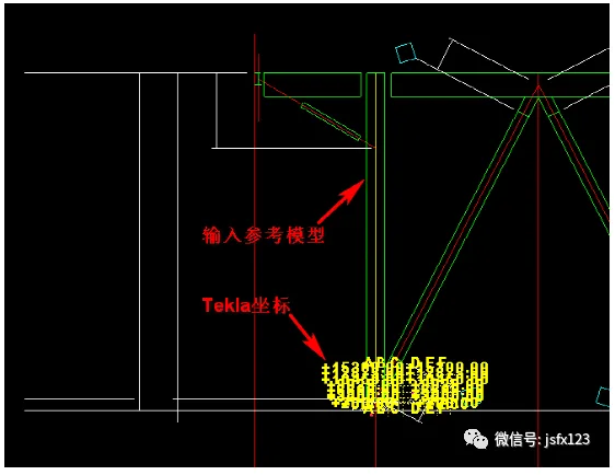
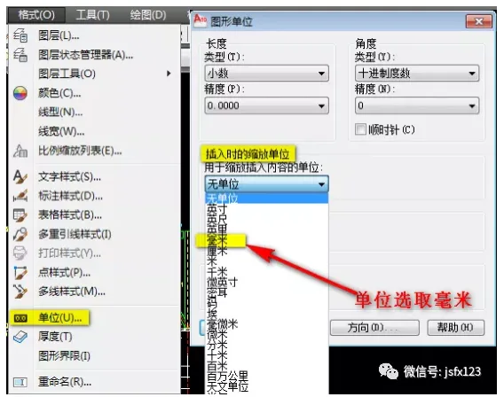
Additionally, make sure the reference model is saved under the correct model target and that the CAD drawing has been properly closed. - Reference model scale distortion when imported at 1:1 in TEKLA:
In CAD, go to Format > Units > Graphic Units, then change the Zoom Unit During Insertion to millimeters.
- Reference model not displayed:

xuebim
Follow the latest BIM developments in the architecture industry, explore innovative building technologies, and discover cutting-edge industry insights.
← Scan with WeChat


Must log in before commenting!
Sign Up