BIM Q&A | How to Create Advanced Lighting Analysis Diagrams in Revit?
For this tutorial, I’m using Revit 2017, but earlier versions will also work. To keep things simple, I’m starting with a sample model provided by Revit.
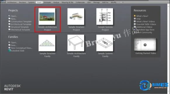
Step 1: Launch Revit and open the pre-built model. This building will serve as our case study for lighting analysis.
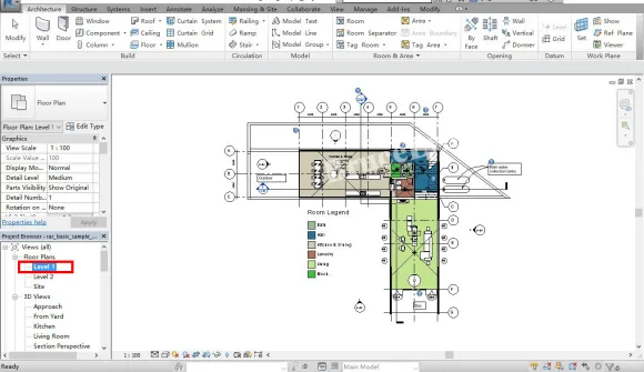
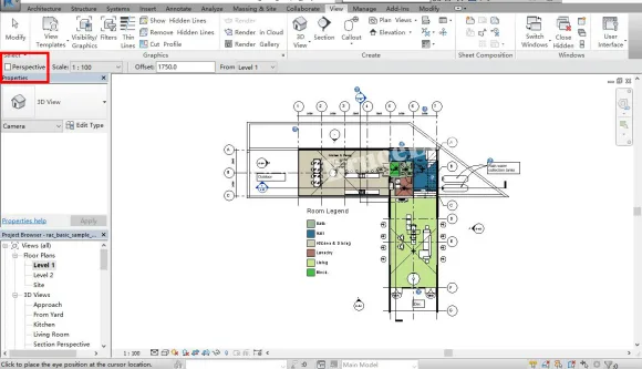
Step 2: Once the file is open, select the floor plan on the left side to enter the first floor plan view. You can also choose the second floor plan if you prefer.
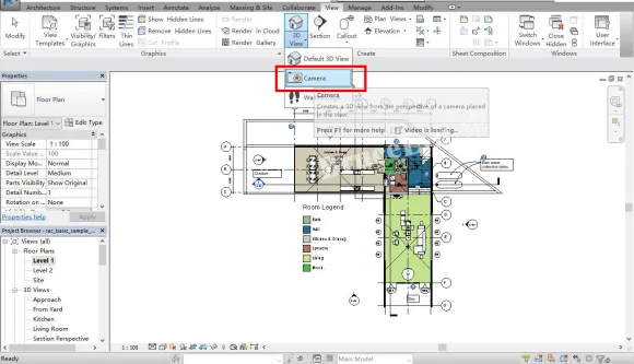
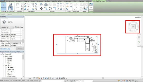
Step 3: Go to the View menu and select the Camera option under the 3D Views submenu. The next steps require careful attention to avoid mistakes.
Step 4: After selecting the camera, make sure to uncheck the “Perspective” option in the left sidebar. This step is crucial—uncheck it thoroughly.
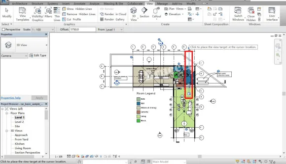
Step 5: Your mouse cursor will change to a camera icon. Click any point on the floor plan and drag to set the camera’s direction and distance—choose this based on your preference.
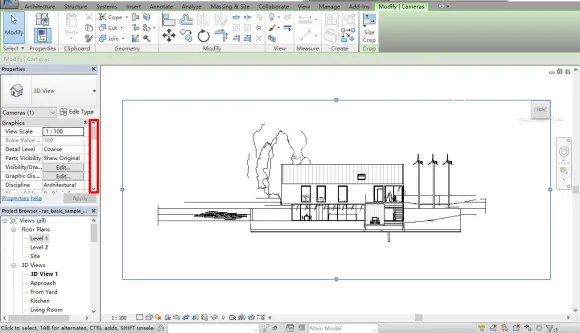
Step 6: Witness the transformation as the floor plan switches to an elevation view. Take a moment to study this view carefully.
Step 7: Look to the view cube in the upper right corner and click the “Top” face to switch to the top view.
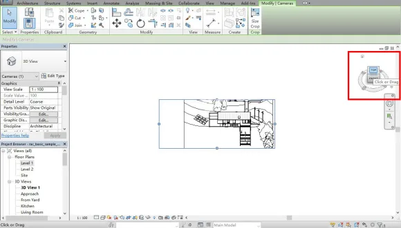
Step 8: With the top view displayed, continue observing the scene quietly.
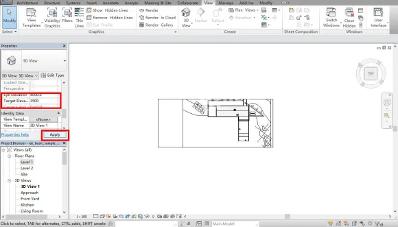
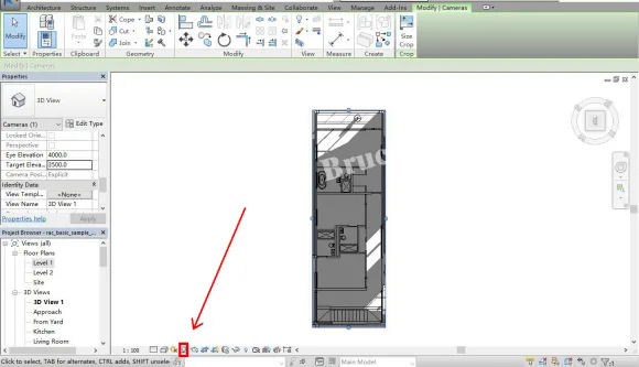
Step 9: Now, focus on the properties panel on the left. Change the Eye Elevation to 4000mm, which is the final viewpoint height for daylight analysis. Since the second floor ranges between 3000-6000mm, any value within this range works. Then set the Target Elevation to 3500mm, ensuring it’s below the Eye Elevation but within the same range. Apply these settings, and the view will transform back to a floor plan, ready for daylighting analysis.
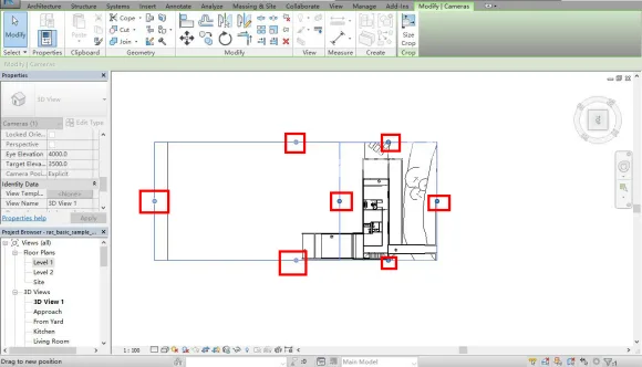
Step 10: After applying the changes, blue control points appear on the floor plan. Drag these points to adjust the analysis area to your desired size.
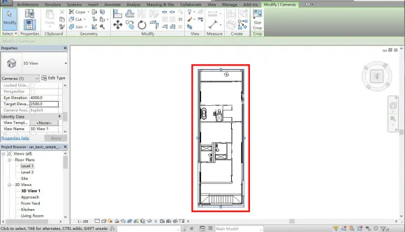
Step 11: For this example, a rectangular area was selected for the lighting analysis.
Step 12: Spot the light bulb icon indicated by the red arrow? Click it to reveal the building’s internal lighting and shadow relationships.
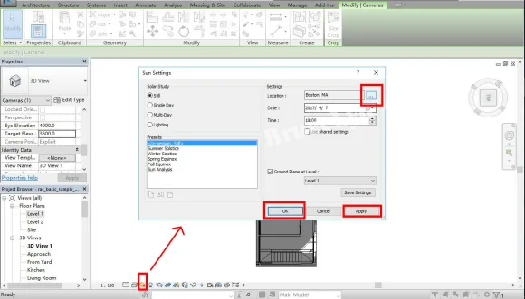
Step 13: Setting the climate data is critical and prone to errors. Click the small sun icon next to the light bulb. A menu bar will appear. Under the “Location” section, click the ellipsis (…) to proceed to the next step.
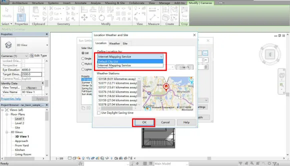
Step 14: In the location menu, you can choose the geographic location in various ways. For this tutorial, I selected a city from the default list. You can also customize locations similarly to Google Maps, but we won’t cover that here.
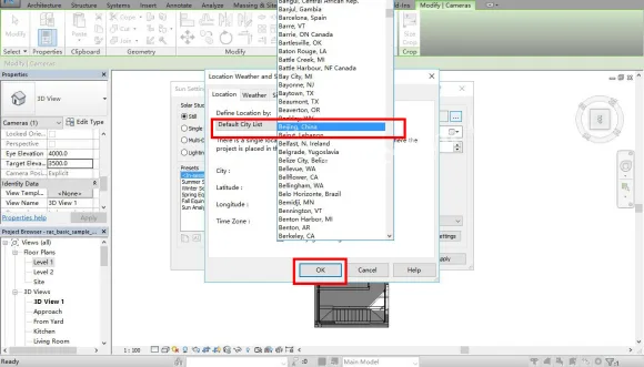
Step 15: Select the city where your project is located. In this case, I chose Beijing—it adds a majestic feel!
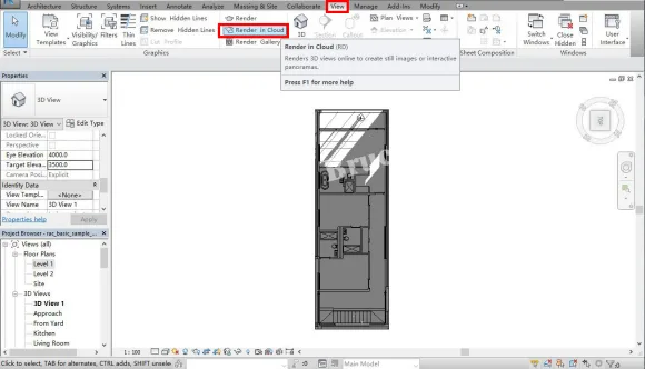
Step 16: After setting the city, the building’s interior shadows will update in real time. Now, return to the View menu and click “Render in Cloud” to proceed to the final steps.
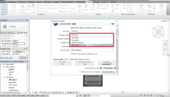
Step 17: In the cloud rendering menu, set the output type to “Illuminance,” which refers to the lighting analysis option we’ve discussed earlier.
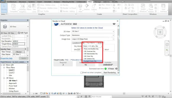
Step 18: After selecting illuminance, update the sky type to “Daylight Factor Sky.” We will explain the differences between sky types in a future tutorial—just remember this setting for now.
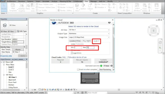
Step 19: Set the illuminance range from 0 (minimum) to 20 (maximum). The reasoning behind these values will be explained later. For now, just keep these numbers in mind as the basis for your analysis.
Step 20: With all parameters set, click the “Start Rendering” button located at the bottom right.

Step 21: Once you start rendering, a progress window will appear. Simply wait a few seconds while the process completes.
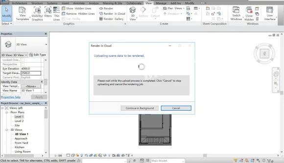
Step 22: Your data will be uploaded to the cloud for rendering, which frees up your computer’s memory. Once finished, click “Render Gallery” under the cloud rendering tab to view the stunning analyzed images. Note: you’ll need to register an Autodesk account using your personal email beforehand. After registration, all Autodesk products will be linked to this account for easy access.
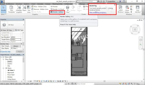
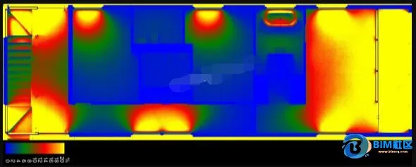
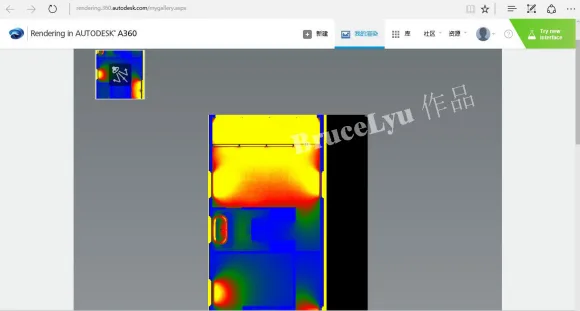
Step 23: Finally, when you open the Render Gallery, a webpage will display your daylighting and illumination analysis diagrams. You can download these images and incorporate them into your design plans.


Must log in before commenting!
Sign Up