1. Steel Bar Sampling
Steel bar sampling involves calculating the total weight of steel bars used in a construction project, typically expressed in tons. The weight is determined by multiplying the total length of the steel bars by their specific gravity. Essentially, steel bar sampling calculates the combined length of steel bars of different diameters, which, when multiplied by their respective specific gravities, gives the theoretical total weight of the steel bars.
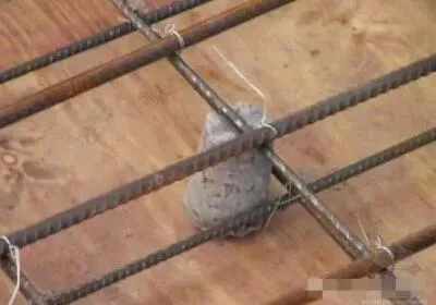
2. Concrete Protective Layer
The concrete protective layer refers to the concrete that surrounds the steel reinforcement skeleton within structural components. The thickness of this layer is the distance from the outer surface of the main reinforcement to the concrete surface (i.e., the outer face of the component). This protective layer must be at least 10mm thick to ensure adequate protection.
3. Types of Steel Bars
Reinforcement in reinforced concrete is categorized by diameter into steel bars and steel wires. Steel bars have diameters of 6mm or more, while steel wires have diameters of 5mm or less.
Production methods include hot-rolled steel bars, waste heat-treated steel bars, cold-drawn steel bars, and cold-rolled steel bars.
Common steel bar classifications (according to GB50010-2002) include:
- HPB235: Hot-rolled round steel bar, first-grade steel
- HRB335: Hot-rolled ribbed steel bars, second-grade steel
- HRB400: Hot-rolled ribbed steel bars, third-grade steel
- RRB400: Waste heat treatment reinforcement, third-grade steel
The grade 540 steel classification is now obsolete and has been phased out.
4. Reinforcement Connection
Steel bars are manufactured in standard fixed lengths (e.g., 9m or 12m). However, actual engineering applications require steel bars of various lengths and shapes, necessitating connections.
Connection methods include:
- Binding and welding (butt welding, single-sided welding, double-sided welding, electroslag pressure welding)
- Mechanical connections (straight thread connections, tapered thread connections, casing cold extrusion)
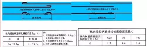
5. Overlapping Length of Steel Bars
The lap length varies by connection type:
- Binding: Lle or Ll
- Single-sided welding: 10 times the bar diameter (10d)
- Double-sided welding: 5 times the bar diameter (5d)
The binding length calculation depends on specific design values.
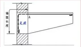
6. Reinforcement Anchoring
The reliability of steel reinforcement in concrete depends on the bond between steel bars and concrete. The longer a steel bar extends into the concrete, the stronger the bond.
The anchor length refers to the length of steel bars embedded into the support to prevent pullout, which must be at least 250mm. Detailed anchorage lengths can be found in design drawings or based on design specifications.
7. Budget Length and Cutting Length
The budget length of a single steel bar is calculated as the sum of each section’s length (including anchorage and overlap lengths) plus any additional length for end hooks (if applicable).
The cutting length is similar but subtracts the bending adjustment value (difference caused by the bending process, also called bending allowance) from the total.
8. Bending Adjustment Value
When a steel bar is bent, the inner side compresses while the outer side stretches, with only the centerline maintaining a constant length. Since measurements typically use the outer layer length, cutting lengths must be adjusted based on the drawing’s pattern dimensions.
Although drawings often show right-angle bends, actual bends must be gradual arcs (slow bends) to avoid damage. Regulations specify the minimum bending diameter (D).
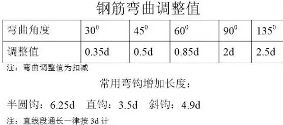
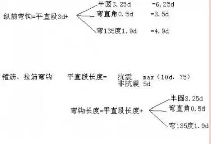
9. Added Length for End Hooks
For detailed calculation methods, please refer to Fu Zhongpeng’s Reinforcement Handbook.
When the bending diameter is 2.5 times the bar diameter (2.5d) and the straight section length is 10d, the added length for bending hooks (such as seismic hoops) are approximately:
- 90° bend: 10.5d
- 135° bend: 11.9d
- 180° bend: 13.25d
10. Factors Affecting Steel Reinforcement Calculations
Several factors influence reinforcement calculations, including:
- Seismic Grade: Higher seismic grades require longer encryption zones in beams. For example, level 1 seismic resistance requires ≥ 2×Hb and ≥ 500mm, while secondary seismic resistance requires ≥ 1.5×Hb and ≥ 500mm. Seismic grade depends on structural type, fortification intensity, and eave height.
- Protective Layer Thickness
- Concrete Grade: For instance, C30 concrete affects anchorage and lap lengths.
- Overlapping Form: Influences the number of stirrups and length of longitudinal steel bars in columns.
11. List of Current Legal Regulations
Flat Method Series Atlas
The flat method involves expressing the dimensions and reinforcement of structural components directly according to overall plane drawing rules. This approach coordinates with standard structural detail drawings to create a simplified, comprehensive design process. It replaces the traditional, cumbersome method of indexing components from layout plans and drawing detailed reinforcement diagrams individually.
Horizontal Classification: Node construction related to columns, walls, and beams.
- 03G101-1: Cast-in-situ concrete frames, shear walls, frame shear walls, frame-supported shear wall structures.
- 03G101-2: Flat staircase construction.
- 04G101-3: Raft foundations and foundation beams.
- 04G101-4: Cast-in-situ floor and roof slab construction.
- 11G101-2: Cast-in-situ concrete slab staircases.
- 11G101-3: Independent foundations, strip foundations, raft foundations, and pile caps.
1. What Are Frame-Supported Beams and Frame Columns?
In Chinese terminology, a frame beam is often called a “transfer beam” in English. This refers to a beam serving as a transition between different structural floors — specifically, a beam supporting the upper shear wall structure over a lower frame structure. The supporting column for this beam is termed a “frame column” in China but is known as a “transfer column” abroad. This difference arises from cultural and linguistic nuances.
2. When and Why Are These Foundations Used?
Simply put:
- Strip Foundation: Supports wall load-bearing structures, mainly for brick walls.
- Independent Foundation: Supports frame structures with columns.
- Belt-Type (Well Format) Foundation: Frame structure combined with poor foundation conditions, using strip foundations to support columns; refers to concrete strip foundations with formwork.
- Raft Foundation: Used for high-rise buildings or heavy loads on weak soils. Includes beam raft and slab raft foundations. Slab rafts act like plates anchored to the ground, suitable for 5-6 story buildings.
- Pile Foundation: Transfers heavy loads to deeper, stronger soil layers. A pile cap is a platform supported by multiple piles that distribute loads from the building.
- Box Foundation: For high-rise or heavy-load structures on weak soil. Composed of bottom and top plates with vertical and horizontal walls; large hollow areas can serve as basements.
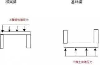
Why Is Negative Reinforcement on the Lower Part of Foundation Beams?
Unlike frame beams, foundation beams act as inverted frame beams. The following image illustrates this concept simply.
Material Self-Weight Comparison
The self-weight of materials is as follows:
- Concrete: 22-24 kN/m³
- Reinforced Concrete: 25 kN/m³
- Steel: 78.5 kN/m³
Despite steel’s higher density, textbooks often state that steel structures are lighter than concrete structures. This is because steel structures achieve comparable strength with about half the material volume needed for concrete. For example, common concrete strengths range from C10 to C80 (C60+ is high strength), while steel typically reaches 200 MPa. Steel exhibits similar tensile and compressive strengths, whereas concrete mainly resists compression and performs poorly under tension.
Calculating Length Based on Outer Layer vs. Centerline of Steel Bars
Cost calculations typically use the length along the outer layer of the steel reinforcement, while cutting lengths are based on the centerline length. For straight bars, these lengths are equal. However, when bars are bent, the outer layer length exceeds the centerline length because the outer surface stretches and the inner surface compresses, with only the centerline length remaining unchanged. The difference between outer length and centerline length represents the increased length due to bending.
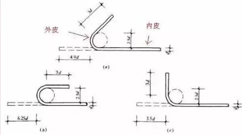
How Is the Length of Bent Steel Bar Hooks Determined?
During construction, steel bars are bent around a “fulcrum” bar with a diameter D equal to 2.5 times the steel bar diameter d. For example, to bend a 10mm diameter bar, a 25mm diameter bar (2.5 × 10mm) is used as the fulcrum.
The hook length equals the sum of the bending length plus the straight section length. The calculation method varies for longitudinal bars, hoops, and tension bars, with differences depending on whether seismic resistance is required.


Must log in before commenting!
Sign Up