Advantages of Aluminum Alloy Formwork
1. Lightweight: Weighs less than 19 kg per square meter.
2. High Strength and Precision: Aluminum alloy formwork provides strong, precise structures with minimal surface joints.
3. Easy Assembly: The formwork can be assembled manually or lifted by machinery as a whole after partial assembly.
4. Standardized Construction: Enables high turnover rates, with normal use reaching up to 300 cycles.
5. Versatile Applications: Suitable for wall formwork, horizontal floor slabs (industrial construction), columns, beams, climbing formwork, and more.
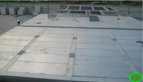
6. Superior Surface Quality: Produces flat, smooth concrete surfaces that can achieve finished or plain concrete effects.
7. Accelerated Construction: Speeds up the construction period by 2-3 times compared to traditional formwork.
8. High Load Capacity: Can bear loads of up to 30 kN per square meter.
9. High Recyclability: Aluminum alloy formwork retains significant residual value, offering clear cost-sharing benefits.
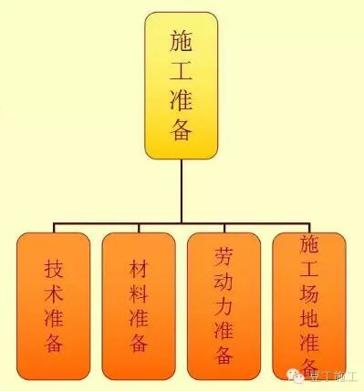
Pre-Construction Preparation
Thorough preparation before construction is essential to ensure smooth production and maintain construction quality.
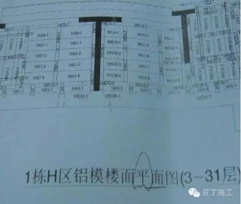
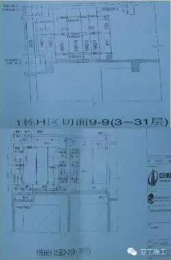
Formwork diagram used for construction.
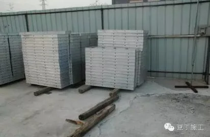
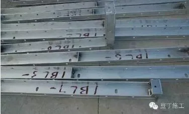
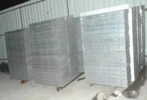
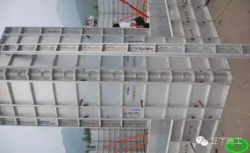
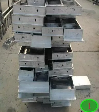
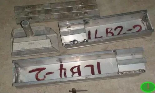
Stacking of standardized small panels, where “B” indicates the floor slab.
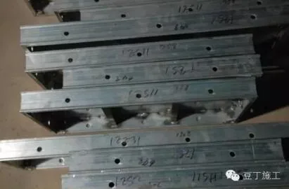
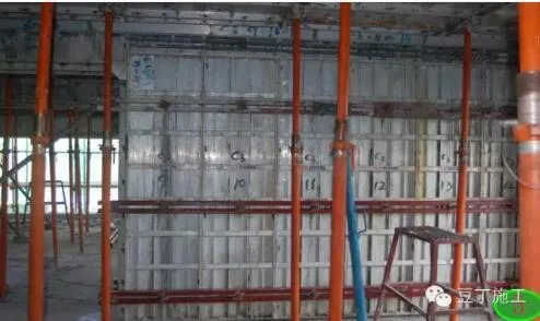
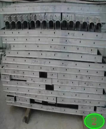
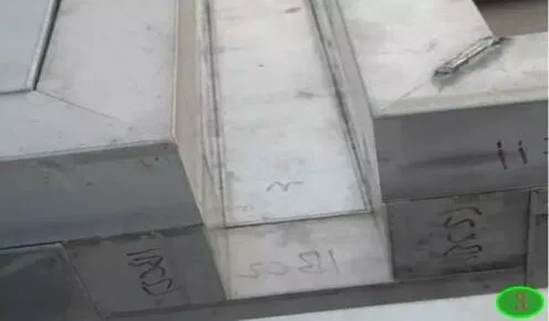
Standardized small wall panels are usually marked with “W” on the border for wall panels and “E” for beam bottoms. The aluminum alloy thickness ranges from 4-8 mm, with a typical size of 398 mm by 1198 mm as shown.
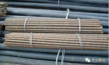
‘R’ represents the reinforcing rod, primarily used for reinforcement similar to steel pipes in wooden molds.
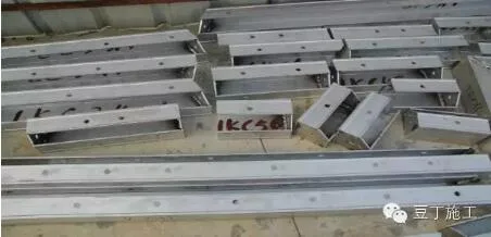
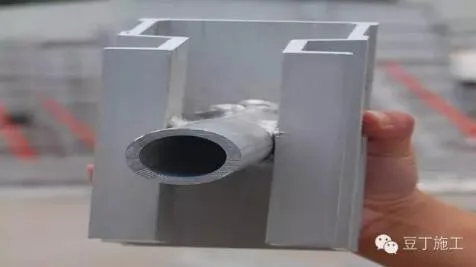
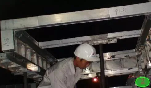
The “C” slot functions mainly in load bearing and transmission, available in various forms for broad applications.
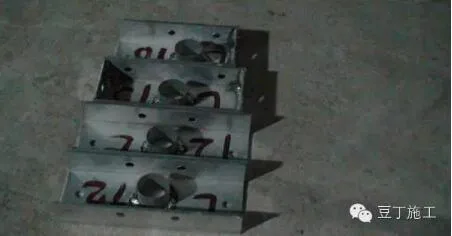
Load component “T” serves to connect and transmit loads within the keel system, often linked to the beam bottom plate using pin iron sheets.
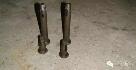
Pins act as fasteners, similar to nails, available in short, medium, and long sizes for various uses.
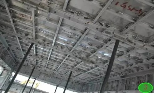
The “keel,” denoted by “B,” connects small boards and is integral to the panel structure.
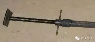
Screws are used for tying and securing wall panels, often encased in PVC pipes for protection.
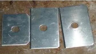
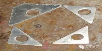
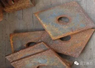
Gaskets are used to increase thickness; when pins and iron plates fail to lock components effectively, gaskets provide the necessary thickness to secure the lock.
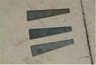
The iron plate functions to lock the pin in place.
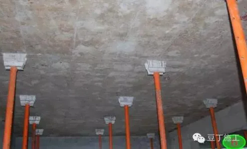
Supports transmit vertical loads efficiently.
The “meteor hammer” connects primarily to the supporting poles and is commonly used beneath the keel.
Pulling wires serve as components during reinforcement, similar to a “mountain buckle” used in construction.
Labor Preparation
Aluminum formwork construction has been used in Hong Kong for over a decade. Operators require minimal woodworking skills and limited experience. After on-site training, teams can typically assemble and operate formwork for two to three floors efficiently. For instance, Guangzhou Wenchong Vanke divides a floor into multiple units, with each unit consisting of around five workers.
Construction Site Preparation
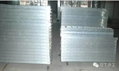
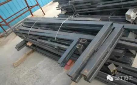
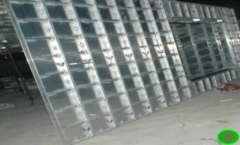
The construction site should be neatly organized, with wall panels and floor slabs stacked separately to facilitate material handling and transportation.
Construction Equipment
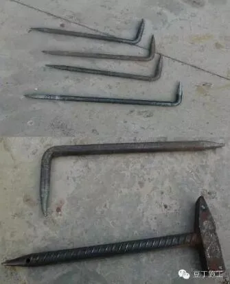
Hammers and hooks are the primary tools used to secure reinforcement dowels.
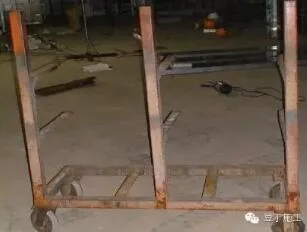
Transport vehicles facilitate the movement and transfer of materials on-site.
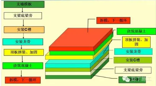
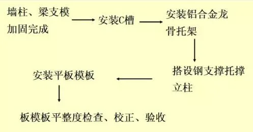
Construction Process Flow
The overall construction sequence is as follows:
Install wall formwork support → Install beam bottom support → Install C-groove → Install keel → Assemble top plate → Reinforce → Pour concrete → Remove formwork and repeat for the next cycle.
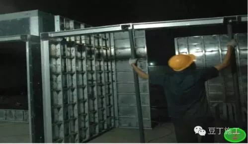

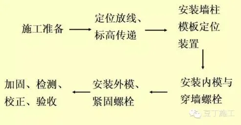
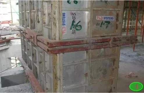
1. Wall and Column Formwork Construction Process
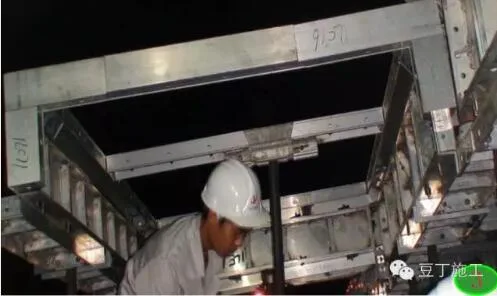
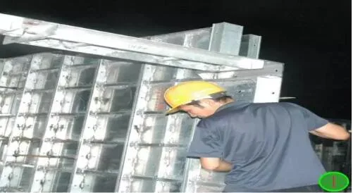
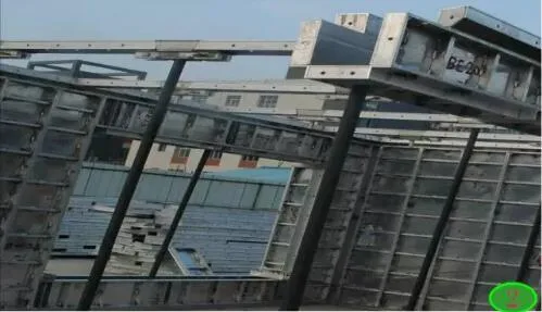
2. Structural Beam Formwork Construction Process
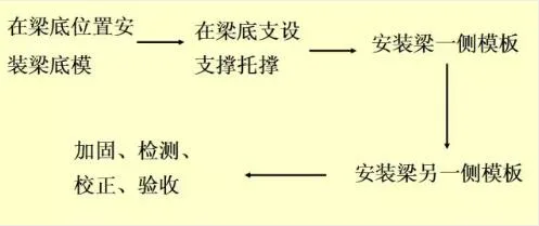
3. Structural Slab Formwork Construction Process
Quality Standards
1. Formwork and its supports must be designed considering the structural form, load magnitude, soil type, construction equipment, and material availability. They should provide adequate bearing capacity, stiffness, and stability to safely withstand the weight, lateral pressure, and construction loads of the concrete.
2. Formwork must be inspected and approved before concrete is poured.
3. The removal of formwork and supports must follow the construction technical plan, including safety precautions.
Note: The dismantling sequence differs from traditional wooden formwork. Remove the plate mold first, starting with the keel, then pins, followed by the plate mold, C-groove, and finally the column mold. Support components should remain in place until the concrete reaches the required strength, typically maintaining 4-6 layers of supporting poles, meteor hammers, and other structural elements during removal.
4. Formwork joints must not leak grout. Formwork should be wetted before pouring concrete but should not have standing water.
5. The contact surface between formwork and concrete must be cleaned and coated with a release agent that does not affect structural integrity or interfere with finishing work.
6. Remove any debris inside the formwork before pouring concrete.
Inspection Method
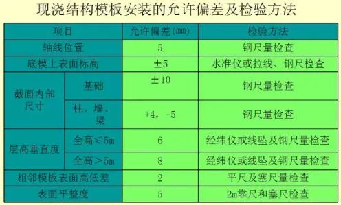
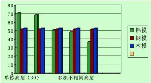
Comparison of formwork schemes
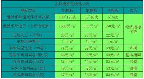
Formwork scheme comparison chart.


Must log in before commenting!
Sign Up