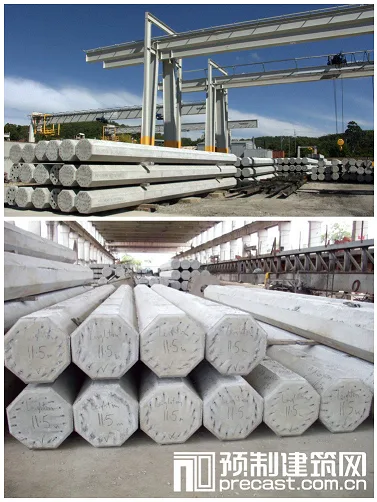
Prefabricated piles are manufactured piles made from various materials and shapes, such as wooden piles, concrete square piles, prestressed concrete pipe piles, and steel piles. These piles are produced either in factories or on construction sites and are installed into the ground by driving, pressing, or vibrating using specialized equipment. In China’s construction industry, the most commonly used precast piles are concrete precast piles and steel piles.
Classification
Prefabricated piles are mainly categorized into two types: concrete prefabricated piles and steel piles. Concrete piles are known for their high load-bearing capacity, strength, durability, and rapid construction speed, making them widely used despite their notable environmental impact during installation. Common concrete types include solid square piles and prestressed hollow pipe piles. Steel piles mainly consist of steel pipe piles and H-shaped steel piles.
Concrete Solid Square Pile
Pile Tip, Body, and Head
Reinforced concrete solid piles typically have a square cross-section that remains consistent along their length. Their cross-sectional dimensions generally range from 200×200mm to 600×600mm. The length of the piles is limited by the height of the pile frame, usually between 25 and 30 meters on site. Factory-fabricated piles are typically no longer than 12 meters due to transportation constraints; if longer lengths are required, piles are made in sections and joined during installation, with no more than three joints per pile.
Advantages of reinforced concrete solid piles include flexible length and size selection, controlled production quality due to ground-level prefabrication, high bearing capacity, and excellent durability. Concrete strength grade should be at least C30 (30N/mm²); for static pressing methods, it can be reduced to no less than C20, while prestressed piles require a minimum of C40. Main reinforcement generally consists of 4 to 8 bars between 12–25mm in diameter, with hoops of 6–8mm diameter spaced no more than 200mm apart. Hoop reinforcement is densified near the top of the pile (2-3 times the bar diameter), and steel mesh is added. A 30mm concrete protective layer is required around the longitudinal reinforcement. Reinforcement can be welded at the pile tip. In dense sand or gravel soil, steel plate pile shoes can be added at the tip for reinforcement.
Concrete Pipe Pile
Concrete pipe piles are typically produced by centrifugal casting in prefabrication plants, available in diameters of Φ300, Φ400, and Φ500mm, with section lengths of 8, 10, or 12 meters. Joints should not exceed four per pile. Each pipe contains 10 to 20 main reinforcement bars (12–22mm diameter) and 6mm spiral hoop reinforcement around the wall, usually made of C30 concrete. Sections are connected by welding angle steel or flange bolts.
The centrifugal casting process expels excess moisture, resulting in dense, high-strength concrete with excellent resistance to groundwater and corrosion. Piles must reach 100% design strength before transport. Stacking is limited to three layers, and wedge-shaped wooden blocks are used to prevent rolling at the bottom pipe edges.
Prefabricated Pile Production
Shorter piles are generally produced indoors at prefabrication plants, while longer piles are often cast outdoors near construction sites. To optimize space, onsite square piles are poured using a stacking method, with a maximum of four overlapping layers depending on ground load and conditions. The casting site must be flat, solid, and free from uneven settlement.
Isolation layers should separate piles to avoid bonding between contact surfaces or adjacent piles. Pouring of upper or adjacent piles should only begin once the lower or adjacent pile concrete reaches 30% of its design strength. If steel reinforcement or pile body dimensions deviate beyond allowable tolerances, the pile may be damaged. The fabrication sequence should align with the pile driving order to minimize curing time.
Concrete pouring must be continuous from the pile top to tip without interruption and should avoid excessive mortar accumulation at the base.
Lifting
Proper Lifting Points for Piles
Reinforced concrete precast piles can only be lifted once the concrete reaches 70% of its design strength and transported or driven after attaining 100%. Premature lifting requires special measures and verification.
Lifting points must be carefully chosen to prevent bending damage during handling. For up to three suspension points, positions are determined by balancing positive and negative bending moments. For more than three points, positions are calculated based on equal reaction forces. Typically, piles 20–30 meters long use three lifting points.
Transportation and Stacking of Prefabricated Components
Piles should be transported from production to the site and installed following the driving sequence. For short distances, crane lifting is suitable; for longer distances, lightweight tracked vehicles should be used. Direct pushing or dragging on site is strictly prohibited.
Transportation and Stacking of Prefabricated Piles
Stacking grounds must be flat and solid. Wooden pads should align with lifting points vertically, and stacking should not exceed four layers. Piles of different specifications must be stored separately.
Prestressed pipe piles can only be shipped after achieving design strength and sunk after 14 days of curing. For sections under 20 meters, two-point binding is used; for longer sections, four-point suspension is required. During transport, wedges prevent rolling, and staggered wooden blocks between layers are forbidden.
Pile Driving Methods
Common pile installation methods include hammering, static pressing, and vibration. The hammering method uses impact energy from a pile hammer to overcome soil resistance and drive piles to the bearing layer. It is the most widely used technique.
Pile driving equipment consists of three main components: the pile hammer, pile frame, and power source.
Types of Pile Hammers
The pile hammer delivers impact force to drive the pile into the ground. Types include drop hammers, single-acting steam hammers, double-acting steam hammers, diesel hammers, and hydraulic hammers.
① Drop Hammer: Typically made of cast iron, lifted by a winch, and released to drop onto the pile head. Weight ranges from 5–20 kN. It is simple, reliable, and suitable for driving piles in cohesive soil or gravel-rich layers. However, it has slow piling speed and low efficiency. Increasing drop height raises impact energy but risks damaging the pile head; thus, a drop height of 1–2 meters is recommended.
② Single-Acting Steam Hammer: Uses steam power to lift a cylinder fixed on the pile top. Steam pressure lifts the cylinder, which then falls by gravity to strike the pile. Weight ranges from 30–150 kN. It offers higher impact force and faster driving speed than drop hammers, suitable for various pile types.
③ Double-Acting Steam Hammer: The piston inside a fixed cylinder moves up and down powered by steam. Steam alternately enters above and below the piston, lifting and releasing it repeatedly to drive the pile into the soil.
④ Diesel Hammer: Uses diesel fuel combustion to generate expanding gases that propel the hammer upward, which then falls freely to impact the pile. Variants include guide rod, piston, and tube types, differing by the moving impact parts.
Pile Frame Types
The pile frame supports the pile and hammer, positions the pile for driving, and guides its direction. Common types include:
① Roller Pile Frame: Moves on two steel rollers rolling over wooden pads. It has a simple design but limited maneuverability, suitable for precast and cast-in-place piles.
② Multifunctional Pile Frame: Offers 360° horizontal rotation, extendable and tiltable guide frames, iron wheels, and track-based mobility. Suitable for various pile construction types.
③ Crawler-Type Pile Frame: Built on crawler cranes with additional guide rods and supports. It offers greater flexibility and mobility than multifunctional frames and suits all pile types.
Piling Sequence
During pile driving, soil compaction from earlier piles can cause displacement or tilting of subsequent piles. To ensure quality and progress and protect nearby structures, an appropriate pile driving sequence must be planned based on pile density, specifications, length, and pile frame mobility.
Before driving, pile foundation axes are established per design, and pile positions are accurately marked. Factors like pile density, foundation elevation, terrain, and soil conditions influence the sequence.
Common sequences include driving piles from one side in a single direction, symmetrically from the center outward in two directions, or from the center outward in all directions.
For small foundation pits, driving proceeds from the center to the edges; for large pits, the area is divided into sections driven independently. Avoid driving from the periphery inward.
Changing driving direction row by row helps prevent uneven soil compression. Interval driving within the same row is also effective. Large pile groups should be divided into zones driven by multiple pile drivers in a logical order, starting with deep piles before shallow ones, larger piles before smaller ones, and longer piles before shorter ones, to minimize displacement and deviation.
Key principles for pile driving sequence:
- Drive from the center toward the periphery
- Start closest to existing buildings and move outward
- Drive deeper piles before shallower ones
- Drive larger cross-section piles before smaller ones
- Drive longer piles before shorter ones
Pile Driving Procedure
Once the pile driver is positioned, lift the pile hammer and cap, then the pile itself, aligning it vertically into the guide frame with a deviation under 0.5%. Secure the hammer and cap along the same vertical axis to ensure vertical driving. Elastic pads should be placed between the hammer and cap, and a 5–10mm gap maintained around the pile top to prevent damage.
At the start, use a small drop height (0.5–0.8m) for light hammering to sink the pile 1–2 meters. After verifying the pile tip alignment, gradually increase the drop height up to a maximum of 1 meter, continuing until the design depth is reached. Diesel hammers should bounce normally during operation. If sudden changes in penetration, tilting, displacement, or severe cracking occur, stop driving and investigate immediately.
There are two pile driving styles: “light hammer with high impact” and “heavy hammer with low impact”. The same work done yields different results. Light hammering causes high impact force but also significant rebound, risking damage and energy loss. Heavy hammering with a shorter drop height produces larger momentum, less rebound, and more efficient penetration. The higher frequency of heavy hammering also facilitates driving through dense soils. Therefore, “heavy hammer low impact” is generally preferred.
Quality Control
Quality assessment focuses on two aspects: meeting design penetration or elevation requirements, and keeping deviations within specification limits.
1. Design Penetration and Elevation
For piles reaching hard or stiff soils (cohesive soil, gravel, dense silt, sand, or weathered rock), penetration depth is the main control metric, referencing pile tip depth or elevation. If penetration is achieved but elevation is not, hammer for an additional three rounds, ensuring average penetration per 10 blows complies with limits. For soft soils, elevation controls pile driving, with penetration as a reference.
The final penetration is the average depth of the last 10 piles driven. It is determined by test piles or initial piles and is a key quality indicator. Measurements must be taken under normal conditions: intact pile top, centered hammer strikes, compliant hammer drop distance, and proper cushioning.
If penetration and elevation measurements conflict significantly, this indicates unexpected soil conditions requiring consultation with the design team for adjustments.
2. Positioning and Verticality
Pile position deviations must comply with the “Code for Acceptance of Construction Quality of Building Foundation Engineering” (GB50202-2002). Steel piles must be aligned at installation, and the pile body must be vertical. The pile, cap, and hammer centerlines must coincide to ensure vertical driving. When extending piles, joint faces must be flat and aligned, with any gaps filled and welded. Foundation excavation after driving must be carefully planned to prevent pile displacement or tilting.
Environmental Impact and Mitigation Measures
1. All construction activities must comply with national environmental protection laws, including regulations on waste discharge and construction waste management. Any violations or damages affecting neighbors or enterprises are the contractor’s responsibility, with no liability on the employer.
2. Solid waste stacking, noise, and emissions must adhere to the Environmental Protection Law of the People’s Republic of China and relevant regulations.
3. Only products with factory environmental inspection certificates and safe levels of radioactivity and harmful substances may be used. Environmentally friendly products should be promoted to ensure a green project.
4. Garbage collection points must be established in living and construction areas for timely waste disposal to designated landfills.
5. Construction roads should be regularly maintained and watered to minimize dust.
6. Construction management should coordinate waste removal, soil disposal, and material clearance promptly to maintain a clean site environment.
Supplier
Shanghai Zhongji Pile Industry Co., Ltd


Must log in before commenting!
Sign Up