Historical Overview
The production of prestressed concrete pipe piles began in the late 1960s at the Fengtai Bridge Factory under the Ministry of Railways. Initially, they manufactured pre-tensioned prestressed concrete pipe piles (PC pipe piles) primarily for railway bridge foundation projects. In the 1970s, they developed and produced post-tensioned prestressed concrete pipe piles.
During the 1970s, especially for the construction of the Baoshan Iron and Steel Plant in Shanghai, a significant number of steel pipe piles were imported from Japan. These piles were costly and demonstrated poor durability. To address the growing demands of port construction, the Third Navigation Bureau of the Ministry of Transport introduced a complete production line for prestressed high-strength concrete pipe piles (PHC pipe piles) from Japan in 1987. PHC pipe piles typically range in diameter from 600mm to 1000mm.
In the late 1980s, Ningbo Zhedong Cement Products Co., Ltd., in collaboration with research institutes, developed pre-tensioned prestressed concrete thin-walled pipe piles (PTC pipe piles) tailored to the weak and muddy coastal geological conditions in China. These piles typically have diameters between 300mm and 600mm.
Between 1989 and 1992, the former Suzhou Concrete Cement Products Research Institute and Panyu Qiaofeng Cement Products Co., Ltd. independently developed domestically produced prestressed high-strength concrete pipe piles by adapting imported production technologies to local conditions. This achievement was recognized as a key national promotion project by the former Ministry of Construction in 1993.
With economic reforms and construction growth, prestressed concrete pipe piles have been widely used not only in railway systems but also in industrial, civil, municipal, metallurgical, port, and highway engineering. In regions like the Yangtze River Delta and the Pearl River Delta, favorable geological conditions have driven a surge in demand, rapidly establishing pipe piles as a significant industry. By the end of 2007, there were over 400 pipe pile manufacturers in China (excluding Taiwan), producing approximately 250 million meters of various pipe piles with an output value exceeding 30 billion RMB. The industry’s auxiliary product sector generates nearly 25 billion RMB annually, making it a vibrant emerging industry. Currently, pipe piles account for about 50% of the national cement products industry’s output value.
Over the past two decades, pipe pile projects have received prestigious awards, including the second prize for scientific and technological progress in the building materials industry and the third prize of national scientific and technological progress. The pipe pile has been designated as a national-level new product and a key promoted product by the former Ministry of Construction. In 2006, with joint efforts from several enterprises and associations, pipe pile products from Zhongshan Jianhua Pipe Pile Co., Ltd., Zhongshan Sanhe Pile Pole Pipe Pile Co., Ltd. (now Baofeng Concrete Pile Pole Co., Ltd.), and Ningbo Zhedong Building Materials Group were listed as China’s famous brand products, marking a new milestone highly praised within the industry.
The evolution of pipe pile production from non-standard methods to today’s advanced processes is supported by a comprehensive standards system, including GB13476-92 and GB13476-1999 for pre-tensioned prestressed concrete pipe piles, JC888-2001 for thin-walled versions, and additional standards covering testing, materials, and components. This development journey has spanned nearly 20 years.
Pipe piles are categorized into post-tensioned and pre-tensioned prestressed types, including PC pipe piles, PTC thin-walled pipe piles, and PHC high-strength pipe piles.
Pre-tensioned prestressed pipe piles are hollow cylindrical concrete components manufactured using pre-tensioning technology and centrifugal forming methods. They consist mainly of a cylindrical pile body, an end plate, and a steel sleeve.
Based on concrete strength and wall thickness, pipe piles are divided into PC piles (minimum concrete strength C50), PTC piles (minimum C60), and PHC piles (minimum C80). PC and PTC piles typically undergo atmospheric steam curing and require about 28 days before driving. PHC piles, however, are steam-cured in high-pressure reactors at approximately 180°C and 10 atmospheres, reaching C80 strength in just 3 to 4 days after demolding.
Specifications
Pipe piles are produced with outer diameters of 300mm, 350mm, 400mm, 450mm, 500mm, 550mm, 600mm, 800mm, and 1000mm. The most commonly produced sizes are 300mm, 400mm, 500mm, and 600mm.
Material Standards
Steel Materials
Prestressed Concrete Steel Bars (PC steel bars)
These steel bars comply with GB/T 5223.3-2005 standards and bear the product code SBPDL 1275/1420. Available in diameters of 7.1mm, 9.0mm, 10.7mm, and 12.6mm, they are packaged in rolls. Key properties include a yield strength up to 1275 MPa, tensile strength up to 1422 MPa, and good elongation (d8 ≥ 5%). The bars have periodic surface grooves (3-6 helical concave lines) to enhance concrete adhesion, matching the bonding performance of 7-strand steel strands.
Made from low-carbon steel, these bars offer excellent spot welding capabilities, facilitating automatic welding during pile production. They also exhibit good upsetting performance, suitable for end upsetting and wire rolling during on-site work. The bars maintain elasticity when rolled, allowing finished products to straighten naturally without additional processing. These bars have undergone rigorous physical and chemical testing and serve as effective substitutes for threaded steel and construction wire.
Pipe Pile Model Example:
PTC-500(70)A-C70-8
Here, 500mm represents the outer diameter, 70mm is the wall thickness, “A” denotes an effective prestress of 4 MPa, “C70” indicates the concrete strength grade, and “8” (in meters) is the length of the pipe pile.
Pipe piles are classified into types A, AB, B, and C based on bending performance or effective prestress values of 4 MPa, 6 MPa, 8 MPa, and 10 MPa, respectively. Calculations must fall within specified ranges, and bending performance should comply with Appendix C. Thin-walled prestressed pipe piles mainly withstand axial compression, with bending performance tailored to lifting and stacking requirements.
Three main types of prestressed pipe piles—PHC, PC, and PTC—represent mature construction technology widely used in industrial and civil projects across the Yangtze River Delta, Pearl River Delta, and Bohai Bay regions. Their simple technology facilitates quality control and construction.
Two primary pile driving methods are employed: static pressure and hammer driving. Currently, static pressure piles dominate in the Yangtze River Delta. For example, a single PHC-500(100) pile in Shanghai can achieve vertical bearing capacities exceeding 2000 kN. The cost of a PHC-A500(100) pile is approximately 105 yuan per meter, with construction costs around 15 yuan per meter.
PHC Pile Characteristics
- Manufactured strictly according to national standard GB13476-92 and Japanese JISA 5337, with concrete strength not less than C80.
- High bearing capacity per pile and wide design flexibility; different diameters can be combined within the same foundation to optimize load distribution.
- Pile sections can be connected to any length without machinery or site constraints.
- Reliable quality with direct monitoring of length and integrity after installation.
- Excellent resistance to hammering and cracking, with strong penetration capability.
- Cost-effective, with unit bearing capacity prices only one-third to two-thirds that of steel piles, also reducing steel consumption.
- Fast and clean construction process.
2. Pile Driving Preparation
2.1 Selecting the Pile Hammer
Choosing an appropriate pile hammer requires considering the pile’s shape, size, weight, burial depth, structural form, soil, and weather conditions. The hammer’s impact energy must overcome pile tip resistance, side friction, and energy loss from rebound. Insufficient energy leads to local buckling of the pile head, hindering installation to design depth. For this project, involving both soft and hard soil layers, an 8-ton steam hammer was selected.
2.2 Selecting the Pile Frame
The pile frame’s setup and installation significantly affect driving efficiency. The D-308S crawler walking pile frame was chosen for its flexible movement, ease of use, and crawler-based running mechanism, which requires minimal road surface preparation.
2.3 Construction Planning and Pile Positioning
Based on geological and foundation geometry data, a logical pile driving sequence is established along with protective measures for nearby structures. Pile positions are measured according to foundation construction drawings.
2.4 Storage and Lifting
Pipe piles require two support points during storage and lifting, with lifting points arranged as shown in Figure 2. Soft cushions like wooden pads are used for storage, and piles must be protected from vibration and impact during handling.
2.5 Determining Pipe Pile Age
The time between pile fabrication and driving should be maximized to ensure concrete strength meets or exceeds design standards. Factory-produced piles are typically delivered at 80% of design strength. Piles are stacked on-site following a “first in, first out” principle to ensure strength requirements are met.
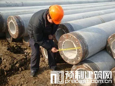
2.6 Inspection and Repair
Before construction, each pile is inspected for quality issues. Both ends should be thoroughly cleaned, and any paint or debris on welding surfaces must be removed.
3. Pile Driving Technical Measures
3.1 Pile Insertion
Since correcting pile angle during driving is difficult, initial placement must be precise. The first pile section should be gently set underground, maintaining correct position and direction. Deviations should be corrected promptly by repositioning or re-pressing. Verticality is verified using two perpendicular theodolites aligned with the pile driver’s guide frame, which can be adjusted by rotation or sliding. Theodolites should be placed away from vibrations and regularly leveled.
3.2 Hammer Impact
Soft soil formations may cause significant initial subsidence. Starting with low-lift, gentle hammer strikes is recommended. As the pile deepens and penetration slows, hammer height can be gradually increased. The hammer, pile cap, and pile body should remain aligned along the same axis. Adjustments to the hammer and guide rods should prevent eccentric impacts that could bend or damage the pile. If driving becomes difficult, check for hammer tilt or inappropriate pile cushions and replace cushions as needed. Continuous driving without interruption is essential to maintain progress.
3.3 Pile Connection
When joining pile sections, axis alignment is critical. Welding surfaces must be cleaned of soil, oil, and rust. Welding is performed when the upper pile section is 1–1.2 meters above ground. Guide hoops attached to the lower pile section facilitate alignment. After positioning, 4–6 symmetrical spot welds secure the connection before removing the guide hoops. Experienced welders must follow technical regulations, using manual welding with E4320 rods—3.2mm or 4.0mm for the first layer with increased current for penetration, and 4.0mm to 5.0mm rods for the second layer—to ensure weld quality.
3.4 Pile Delivery
Driving piles to design elevation requires a pile driver, typically a 4-meter-long steel plate device designed to minimize driving resistance, ease withdrawal, effectively transfer impact force, and allow reuse.
4. Pile Driving Records and Monitoring Surroundings
Detailed records are kept during pile driving, including hammer blows per 0.5–1 meter, pile position deviations, average penetration per 10 blows, and hammer blows per last meter.
Continuous monitoring of nearby buildings for settlement or uplift is critical. Observation points are established on structures, with fixed distant benchmarks for comparison. In one case, no settlement or uplift occurred on a guesthouse located 3 meters east of the podium building; only minor roof cracks were observed. After over a year of use, the guesthouse remains structurally sound.
5. PHC Pipe Pile and Foundation Base Plate Connection Technology
To prevent foundation flotation and ensure coordinated interaction between the foundation and pile foundation, a connection method (see Figure 5) was implemented before tying the raft foundation steel bars. After excavating to design elevation and exposing the pipe piles, debris was cleared from the pile holes. Eleven sheets of plywood formed the bottom mold, suspended with 12-gauge iron wire. Steel bars were tied per specifications, and concrete (minimum C40) with 10% UEA expansion agent was poured. Anchor bars of pipe piles and foundation bottom plate steel bars were firmly welded, ensuring solid structural integration.
6. Test Pile Procedures
6.1 Testing Requirements
Vertical compressive static load tests were conducted before pile driving to verify single pile bearing capacity. Three groups were tested: the first with one test pile and six anchor piles, the second with one test pile and four anchor piles, and the third with one test pile and four anchor piles. Maximum preload values were 6200 kN, 5000 kN, and 4000 kN respectively.
6.2 Testing Standards
Testing followed the “Technical Code for Building Pile Foundations” (JQJ 94-94), using the slow maintenance load method for vertical compressive static load tests.
6.3 Equipment and Loading Duration
The vertical static compression tests used an anchor pile crossbeam reaction device. Two 5000 kN hydraulic jacks, powered by an electric oil pump, applied loads. Load was monitored via sensors, displays, and a precision oil pressure gauge. Settlement was measured simultaneously with electric displacement and mechanical gauges. Data were recorded and processed by computer, with testing performed in an air-conditioned enclosed space to avoid interference.
Tests began no sooner than 10 days after pile installation.
6.4 Test Results
All tested piles were production piles. In the first test, at 4960 kN load, settlement rate sharply increased after one hour to 16.67 mm/h with total settlement of 38.06 mm, indicating failure; thus, the test was stopped. Ultimate load was determined as 4340 kN from Q-s and s-lgt curves.
The second test pile reached 5000 kN at the 9th level, with settlement rising to 15.25 mm/h after 45 minutes and total settlement of 36.51 mm, indicating failure; ultimate load was 4500 kN.
The third pile was loaded to 4000 kN, then 4800 kN after stabilization; loading stopped thereafter, with ultimate load at 4800 kN.
Average characteristic values calculated: Qum = 4547 kN, Sn = 0.052, confirming the standard vertical ultimate bearing capacity Quk = 4547 kN, meeting design requirements.
7. Construction Insights
(1) Using a “heavy hammer with low striking speed” effectively reduces hammering stress. Hammering speed correlates with stress wave intensity in the pile, so employing a heavy 8-ton hammer at lower speeds achieved good results.
(2) The pile head cushion impacts hammering stress directly. Selecting suitable, soft, thick wooden pile pads prolongs hammering duration and reduces stress, yielding positive outcomes.
(3) A well-planned pile driving sequence minimizes lateral pile displacement and limits impact on adjacent buildings. Lateral displacement is common in soft foundations but can be controlled by systematic construction plans.
For regular foundation shapes, driving proceeds symmetrically from the center outward, maintaining compressive stress balance. In this project, the sequence involved driving deep piles for main buildings first (24m), followed by shallow piles for ancillary structures (9m). Mid-span piles precede boundary piles; nearby piles precede distant ones; piles adjacent to buildings are driven before those farther away. These measures effectively reduced lateral displacement.
(4) Installing an anti-seismic ditch reduces impact on neighboring structures. Near the podium building, a 0.8m-wide, 2m-deep ditch filled with yellow sand was excavated adjacent to a strip reinforced concrete foundation only 2.5m from the basement exterior wall. Observations confirmed no adverse effects during construction.
(5) PHC piles, made from high-strength C80 concrete with prestressed spiral reinforcement, offer excellent crack resistance and durability. Only two piles broke during construction, and repairs were straightforward and rapid.
(6) Using PHC piles supports clean, civilized construction sites.


Must log in before commenting!
Sign Up