The Olive Mountain Quick Map features six main tools.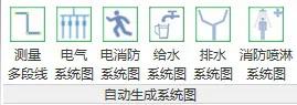
1. Measure the Length of Polylines
Start measuring by clicking the “Measure the length of polylines” button. Then, click sequentially on the endpoints of the polyline. Relevant data will be displayed in the status bar at the bottom left. When finished, press the “ESC” key to view the measurement results.
2. Generate Electrical System Diagram
Note: For best results when drawing floor plans, use the distribution box family provided by us.
After completing the floor plan, create a new legend view under “Legend” in the Project Browser, such as “Legend 1” shown below:
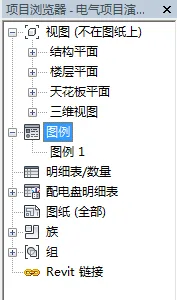
Double-click “Legend 1” to set it as the current view. This applies to all system diagrams introduced later.
Next, click the “Electrical System Diagram” button. A dialog box will appear, allowing you to select the diagram orientation as shown below:
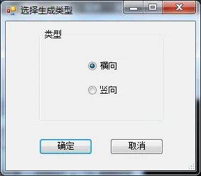
Choose between horizontal or vertical system diagrams, then click “OK” to generate the diagram.
3. Generate Electrical Fire Protection System Diagram
Click the “Fire Protection System Diagram” button to create the corresponding system diagram.
4. Generate Water Supply System Diagram
To generate a water supply system diagram, ensure the pipes in the plan are fully connected with the inlet end open, and no other openings elsewhere.
The program identifies the water supply system based on the system name of the water pipes. The system name should include terms like “cold water system”, “water supply system”, etc. You can view and edit the system name in the appendices.
Click the “Water Supply System Diagram” button, and the following dialog box will appear:
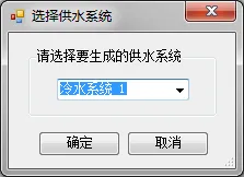
Select the system to generate from the drop-down menu, then click “OK” to create the diagram.
5. Generate Drainage System Diagram
The program recognizes the drainage system by the water pipe system name, which should include terms like “drainage system” or “sewage system”. You can view and modify the system name in the appendices.
Click the “Drainage System Diagram” button to generate the drainage diagram.
6. Generate Sprinkler System Diagram
The sprinkler system is identified by the water pipe system name containing the word “sprinkler”. You can review and adjust the system name in the appendices.
Click the “Fire Sprinkler System Diagram” button to generate the sprinkler system diagram.


Must log in before commenting!
Sign Up