BIM technology has become a hot topic in the construction industry in recent years. However, many industry insiders believe that it will not be widely promoted or adopted. This skepticism stems from two main reasons: first, BIM software developers stand to gain significant economic benefits by promoting their products to owners; second, training institutions hype the current shortage of BIM talent, portraying these professionals as the future stars of the construction industry with unlimited potential.
But is this really how BIM implementation unfolds? What is the true value of BIM technology in real-world applications? In my view, practical outcomes are the ultimate test. Any new technology that truly delivers economic value to owners has unquestionable merit.
Here, I would like to share the practical benefits of using BIM technology based on a project where I personally applied it. This project is one of the four BIM pilot projects commissioned by Guangzhou Metro Corporation.
1. Project Overview
The Guangzhou Metro Line Network Operation and Management Command Center (referred to as the Command Center) spans three plots divided by planned roads into northern and southern sections. The total construction area is 310,000 square meters. Key structures include Tower 1—a 200m office building for the Metro Command Center, Tower 2—a 120m office building, Tower 3—a 112m office building, alongside the COCC line network control center, commercial podium, and supporting podium. The basement covers 92,674 square meters. The project owner is Guangzhou Metro Corporation, construction is managed by China Railway Construction Group Guangzhou Branch, and the BIM consulting services were provided by Shenzhen Zhuzheng Construction Engineering Technology Co., Ltd.
2. Project Challenges
This project involves over 20 disciplines, including architecture, structural engineering, interior decoration, curtain walls, plumbing, electrical, fire protection, HVAC, high and low voltage distribution, and weak current systems. The pipelines across these systems are complex and intertwined. Moreover, the design institute did not account for the spatial coordination between disciplines during blueprint creation, leading to frequent clashes among structures and pipelines during construction. This results in extensive demolition, rework, work stoppages, and material waste, causing significant economic losses and contradicting national green construction initiatives.
3. Value of Applying BIM Technology
1. Blueprint Verification
At the project’s early stage, we used the full set of construction drawings from the design institute to build models. This enabled multidisciplinary design verification based on the models, allowing us to identify and eliminate errors, omissions, and clashes before construction started. For example, in the drawings, the stair starting positions and fire door placements did not align with the floor plan.
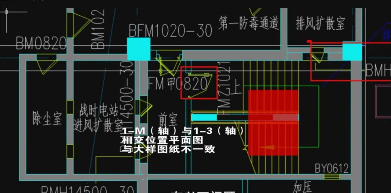
Basement Level 3 Floor Plan (building area)
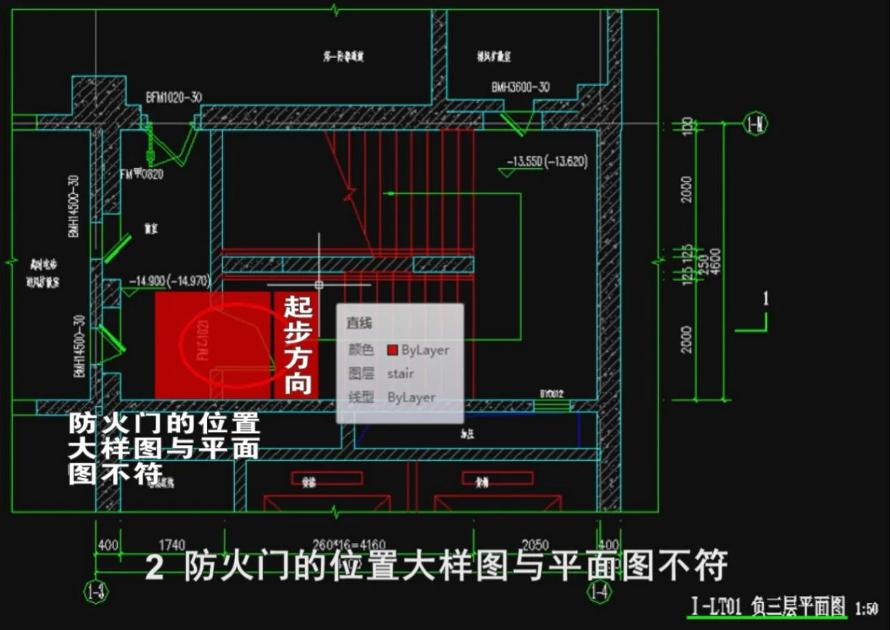
Building Sample
These issues were addressed during drawing review, and the design institute was notified to update the designs before construction. Timely resolution prevented delays, rework, and waste, improving project quality and increasing first-time installation success rates. Shenzhen Zhuzheng Construction also provided BIM model operation training to construction and supervision teams, fostering effective collaboration.
2. Clash Detection and Design Optimization
Clash detection, detailed design, and pipeline integration using BIM models are significant sources of economic benefits for construction parties and owners. This process reduces rework, lowers costs, and minimizes design changes, resulting in smoother construction and better capital management.
Typically, designers from various disciplines independently produce their drawings, making interdisciplinary conflicts inevitable. In this Command Center project, BIM technology identified 7,482 clashes across specialties, with over 100 clashes considered acceptable by regulations. The rest required rerouting to avoid conflicts. Each clash was estimated to cost about 150 yuan. Resolving these clashes upfront saved the owner over 1.17 million yuan, not counting other related cost savings.
Some representative examples include:
1) Architecture and Structure Clashes
① An escalator collided with a beam, and a column penetrated the escalator area. After design coordination, the escalator position was adjusted.
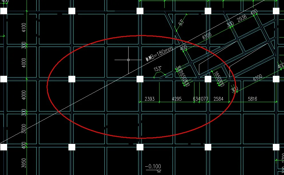
Figure 1: Beam Plane Positioning Diagram
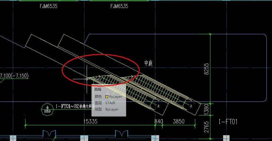
Figure 2: Escalator Plan Positioning Diagram
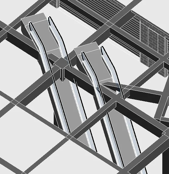
Figure 3: REVIT Model Screenshot
② The water inlet pipe in the basement pump room on level B3 conflicted with the lane structure on B2. After coordination, the water tank was moved left and the pump positioned on the right to resolve the conflict.
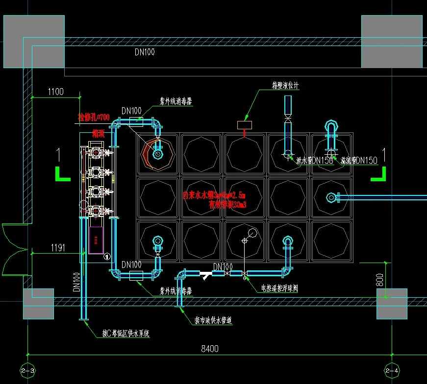
Figure 4: CAD Detail of Water Pump Room
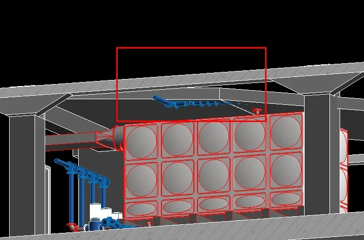
Figure 5: Model Built According to CAD Detail
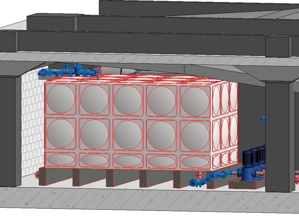
Figure 6: Optimized Model Screenshot
2) Equipment Clashes
① Collision detection of mechanical and electrical pipelines revealed many overlapping conflicts. By rerouting, these pipeline clashes were resolved one by one.
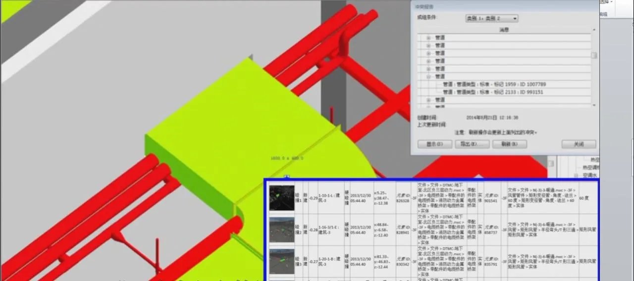
From the initial CAD drawings, it is evident that architects did not fully consider the beam and column arrangements from structural design, leading to these conflicts. After reporting, the design unit modified the design, adjusting beam reinforcement and escalator installation plans. Structural modifications require extensive recalculation and analysis, so early detection avoids costly delays and material waste. Thus, resolving these clashes saved significant costs for both the construction and owner units.
3. Application of Comprehensive Pipeline Layout Technology in BIM
The comprehensive balance technology for pipeline layout is a construction management method applied to building electromechanical installations, including ventilation, plumbing, electrical, and intelligent control systems. This technique uses computer modeling to preassemble pipelines, identify and resolve conflicts before construction, and effectively reduce rework to zero. Its implementation shortens construction timelines, avoids overlapping and improper connections, improves quality, and delivers economic benefits.
In the Command Center project, this technology achieved:
1) Rapid improvement of node and construction detail design. Using the REVIT model, sectional views were created at key locations to generate detailed drawings guiding mechanical and electrical installation. For example, installation on the 7th-floor walkway of Tower C was guided by such sectional views.
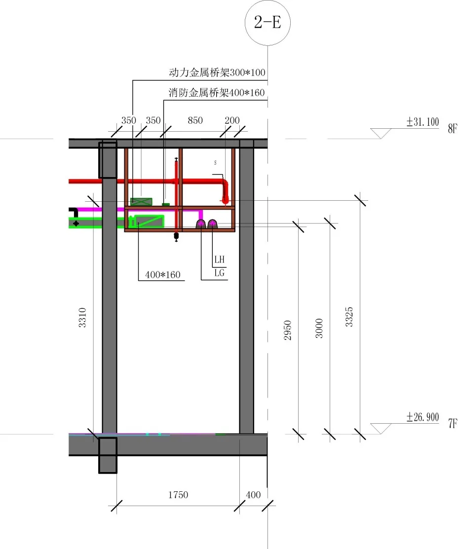
Figure 7: Sectional View at 7th Floor Walkway, Tower C
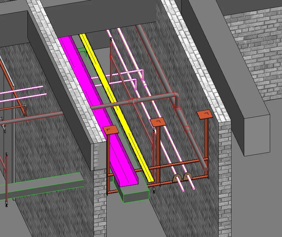
Figure 8: Perspective View of Model at Same Location
2) Resolution of elevation and positioning conflicts of pipeline equipment while maintaining functionality. Adjustments ensured pipelines met clearance requirements, complied with installation sequence, and accounted for maintenance access. For instance, where the air duct at axis intersection 1-4 and 1-E failed to meet the minimum height of 2.3 meters, the duct’s cross-sectional height was modified without changing its area.
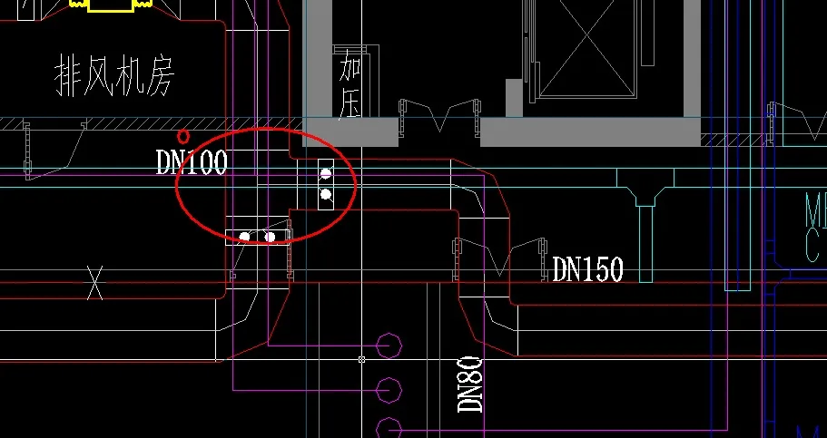
Figure 9: Duct Positioning Diagram
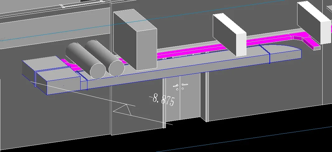
Figure 10: Perspective View of REVIT Model
3) In the computer room, pipelines were reorganized to improve operational space. Initially, the walkway of the chiller unit was only 1.25 meters wide, insufficient for maintenance and aesthetics. After rerouting pipelines to turn into rows, the walkway widened to 3 meters.
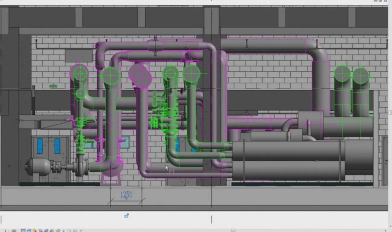
Model Before Adjustment
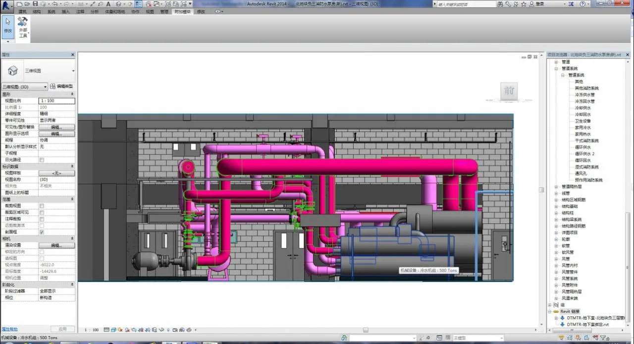
Model After Adjustment
4) On the seventh floor of Building 3, a standard floor with only a 1.75-meter walkway and many pipelines, the layout was adjusted to layer air ducts and cable trays, creating a 400cm maintenance space for insulation, wiring, and repairs.
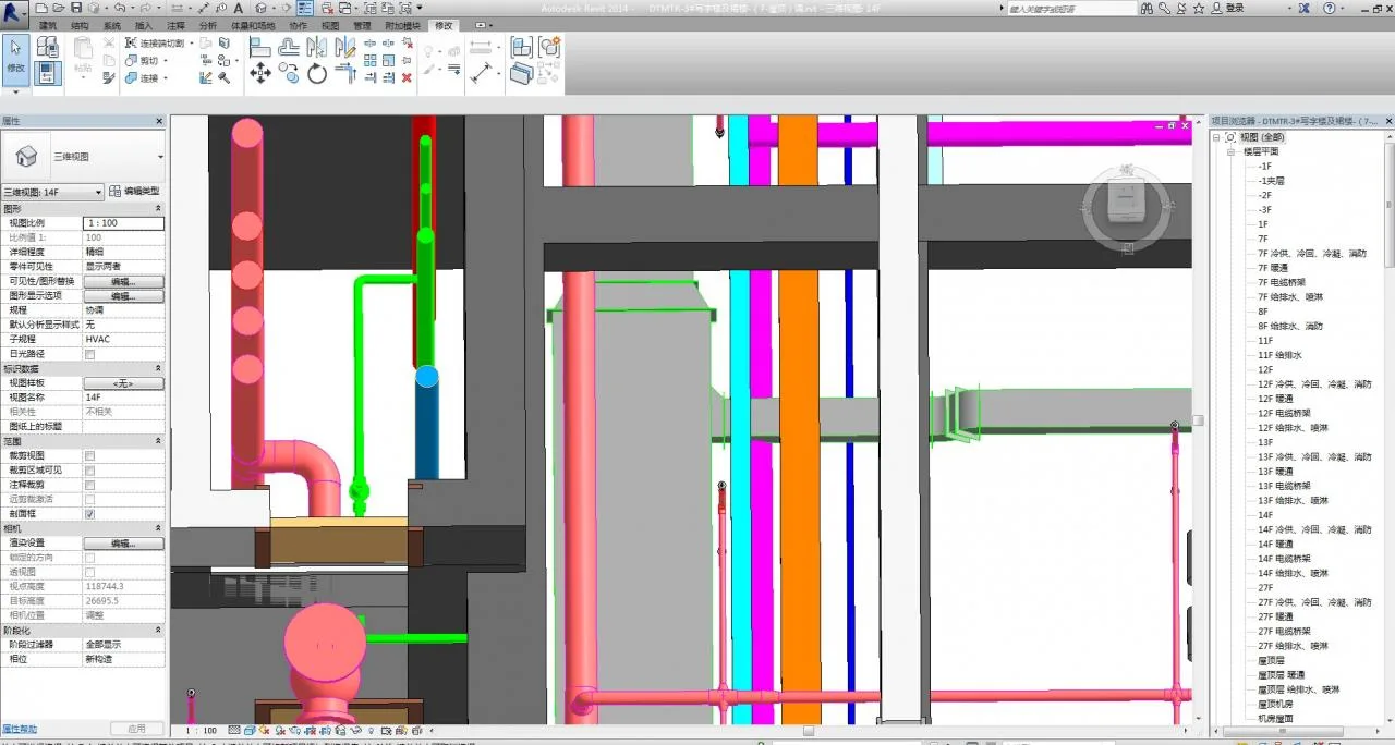
Before Adjustment (No Maintenance or Insulation Space)
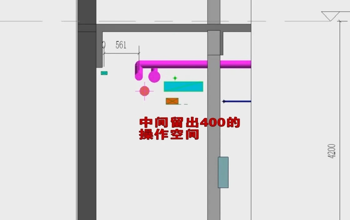
Adjusted Profile
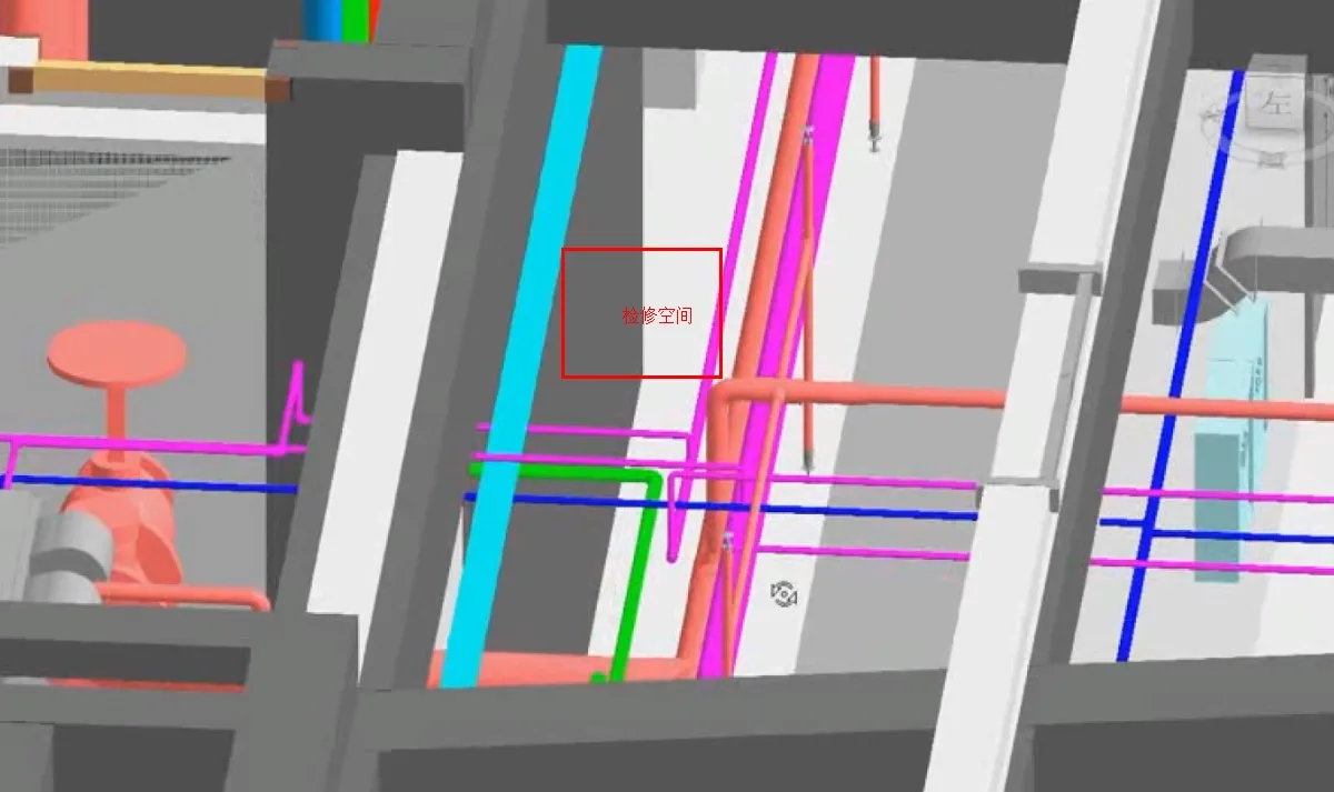
Adjusted 3D Visualization
5) The original basement design specified a minimum clearance of 2.7m for fire sprinkler pipes. After BIM-based adjustments, this was increased to 2.9m, optimizing material use. The average length of DN25 pipes connecting sprinkler heads was reduced by 150mm across 15,410 heads, saving 2,311.5 meters of pipe material. At 20 yuan per meter, this resulted in material cost savings of 46,230 yuan.
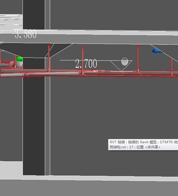
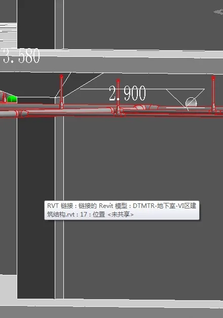
Figure 11: Unoptimized Model Screenshot Figure 12: Optimized Model Screenshot
6) Proactive cost control was enabled by clearly defining pipeline spatial relationships. Using comprehensive support and hanger systems reduced dismantling and modification work post-construction, lowering labor costs and losses.
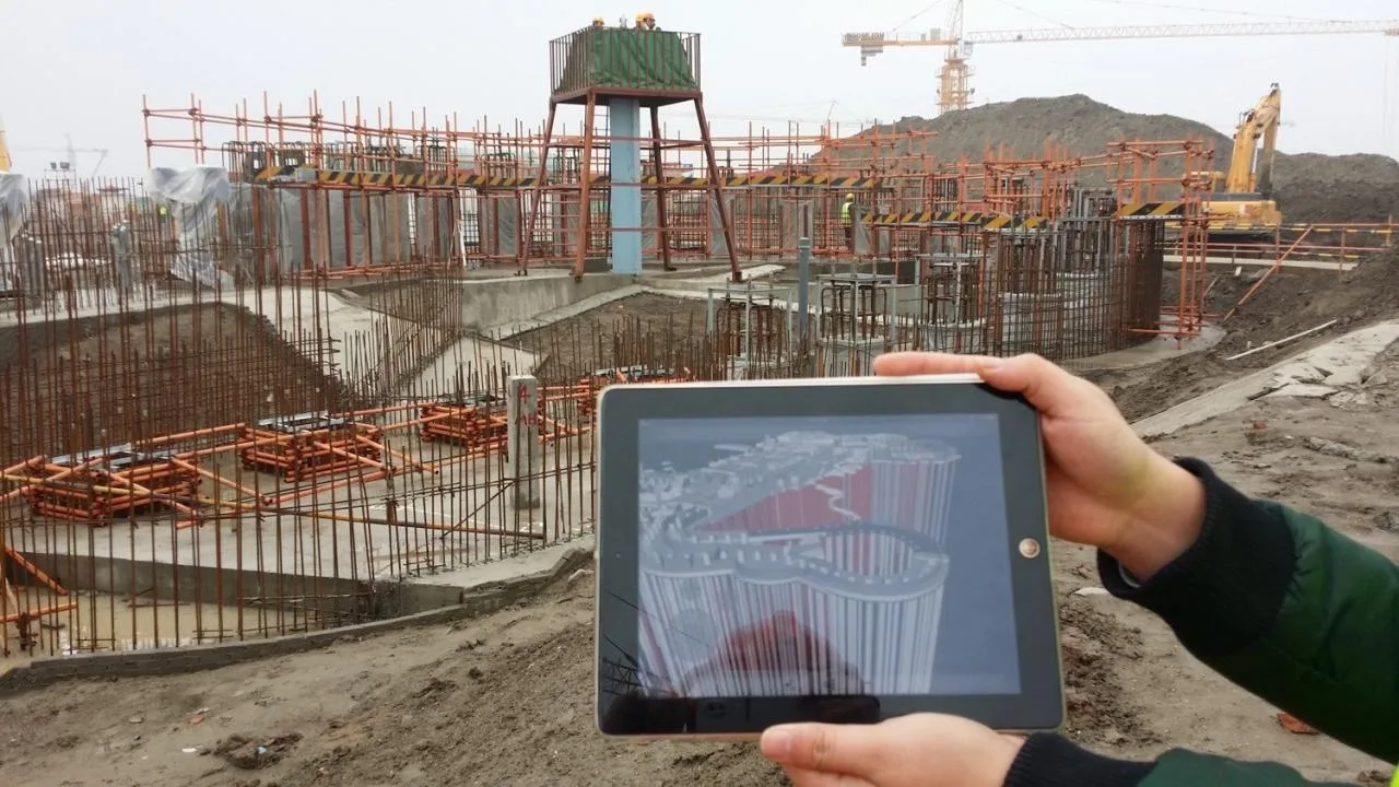
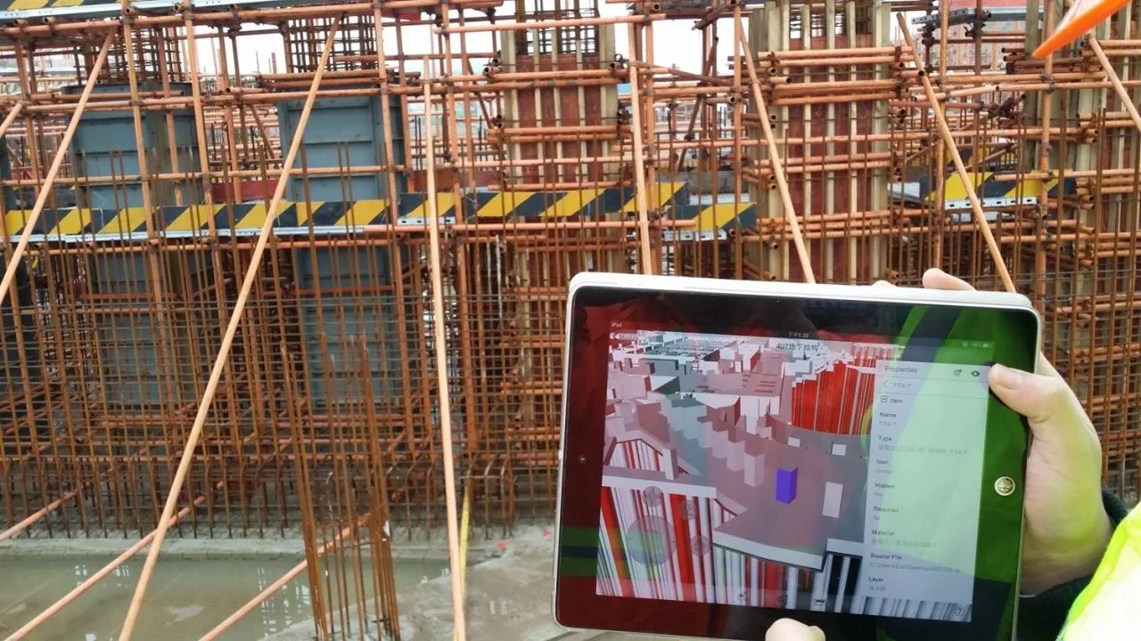
4. Visual Communication
Traditionally, communication between designers and construction teams relies on floor plans and spatial imagination, demanding extensive expertise and often leading to misunderstandings during implementation. These discrepancies cause rework and substantial financial losses. BIM visualization technology simplifies drawing review, on-site technical briefings, and inspections (using devices like iPads), greatly enhancing communication accuracy and minimizing design changes and construction costs, aligning with green construction principles.
5. Roaming Simulation
The initial site layout simulation includes circulation routes (circular lanes, tower crane rotation paths) and safety inspections. The on-site circular lane is 8 meters wide, allowing two vehicles to pass simultaneously. Two gates ensure smooth vehicle entry and exit, meeting fire safety regulations. Seven tower cranes are strategically placed to cover all lifting requirements.
6. 4D Construction Simulation
Progress simulation facilitates scientific allocation of personnel, materials, and equipment. By integrating project management software, a realistic schedule is generated. Before construction, NavisWorks’ 4D virtual construction function simulates progress by zones and building sections, allowing schedule feasibility assessment.
7. Construction Drawing Guidance
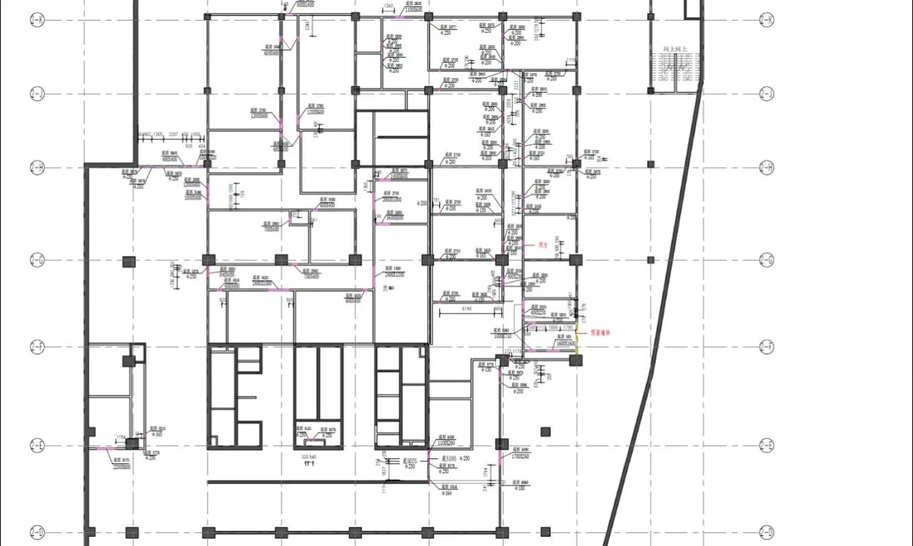
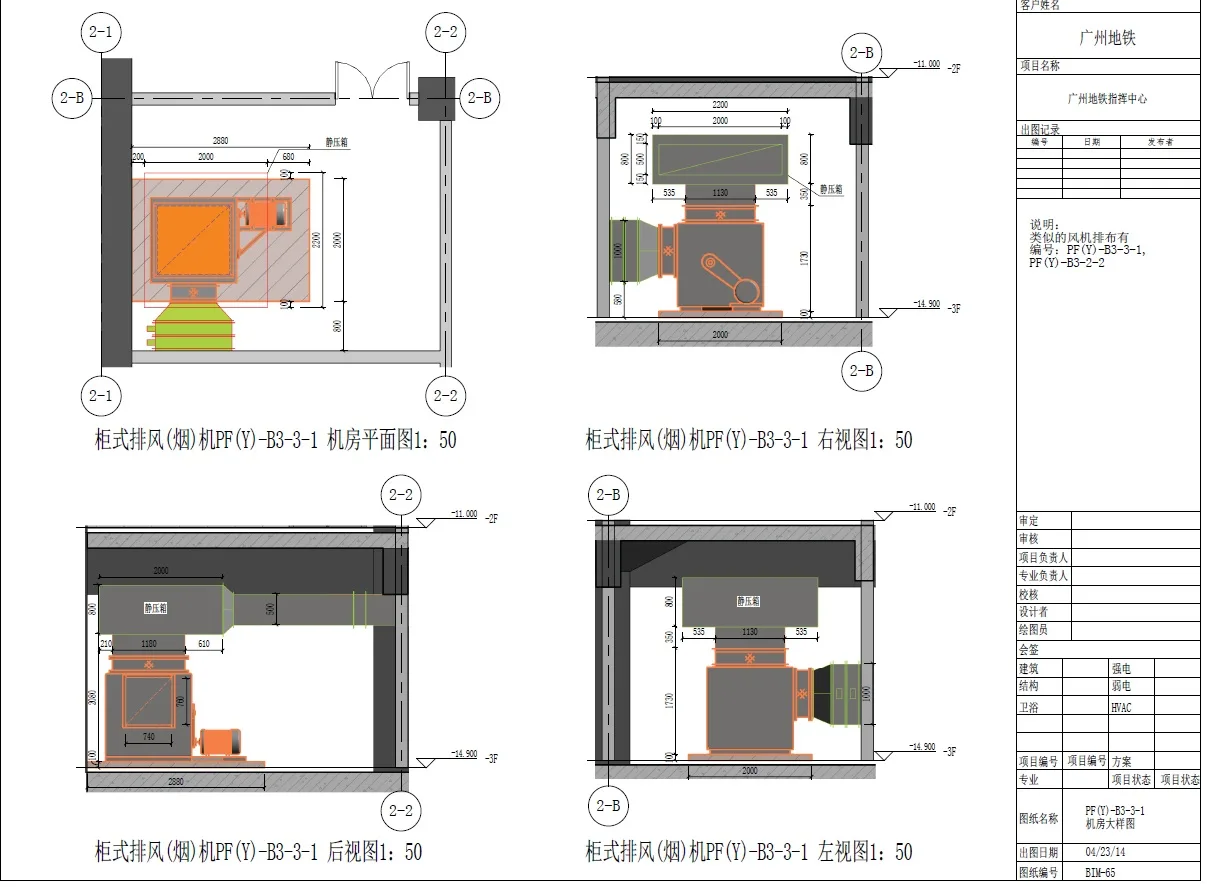
Thanks to the comprehensive pipeline layout technology applied in the REVIT model, the model closely matches the actual pipeline layout on site. REVIT was used to generate construction drawings guiding pipeline and equipment installation. Major drawings included basement pipeline schematics, detailed HVAC room plans, fan room details, sectional views, and reserved hole drawings. These precise documents ensured construction quality and timeline adherence.
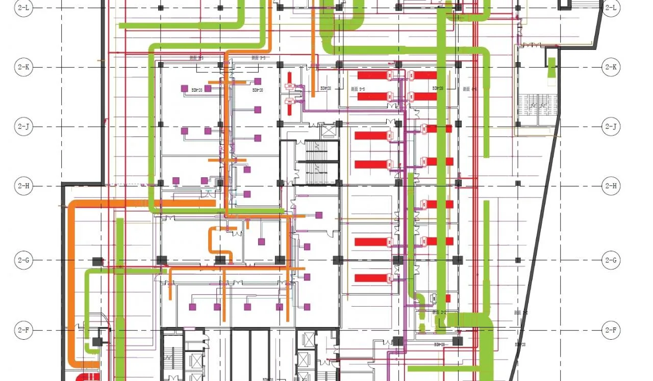
Pipeline Comprehensive Plan
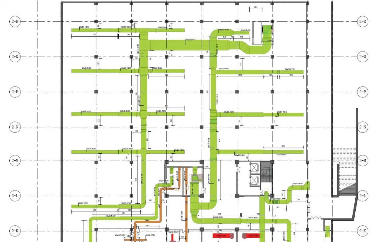
HVAC Construction Guidance Plan
Reserved Hole Plan
Detailed Drawing of Computer Room
8. Refined Design
Refined design represents the future direction of architectural design. Our models incorporate comprehensive parameter data for each component. For instance, the family components of the HTFD-T-B energy-saving, low-noise fan casing include all required design parameters. Additionally, links to manufacturer websites provide up-to-date pricing and technical specifications.
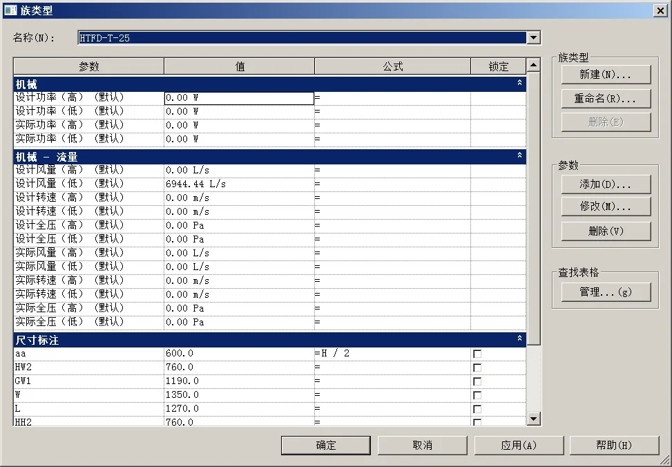
Figure 11: Attribute Data of HTFD-T-B Energy-Saving, Low-Noise Fan Case
4. Comparison Between Model and On-Site Construction
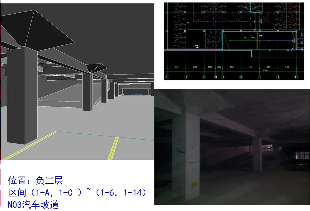
Figure 12: CAD Drawing, Model, and Construction Site – Basement Level 2
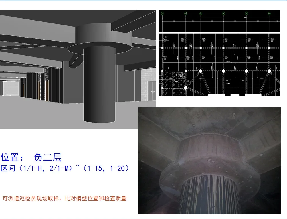
Figure 13: CAD Drawing, Model, and Construction Site – Basement Level 2
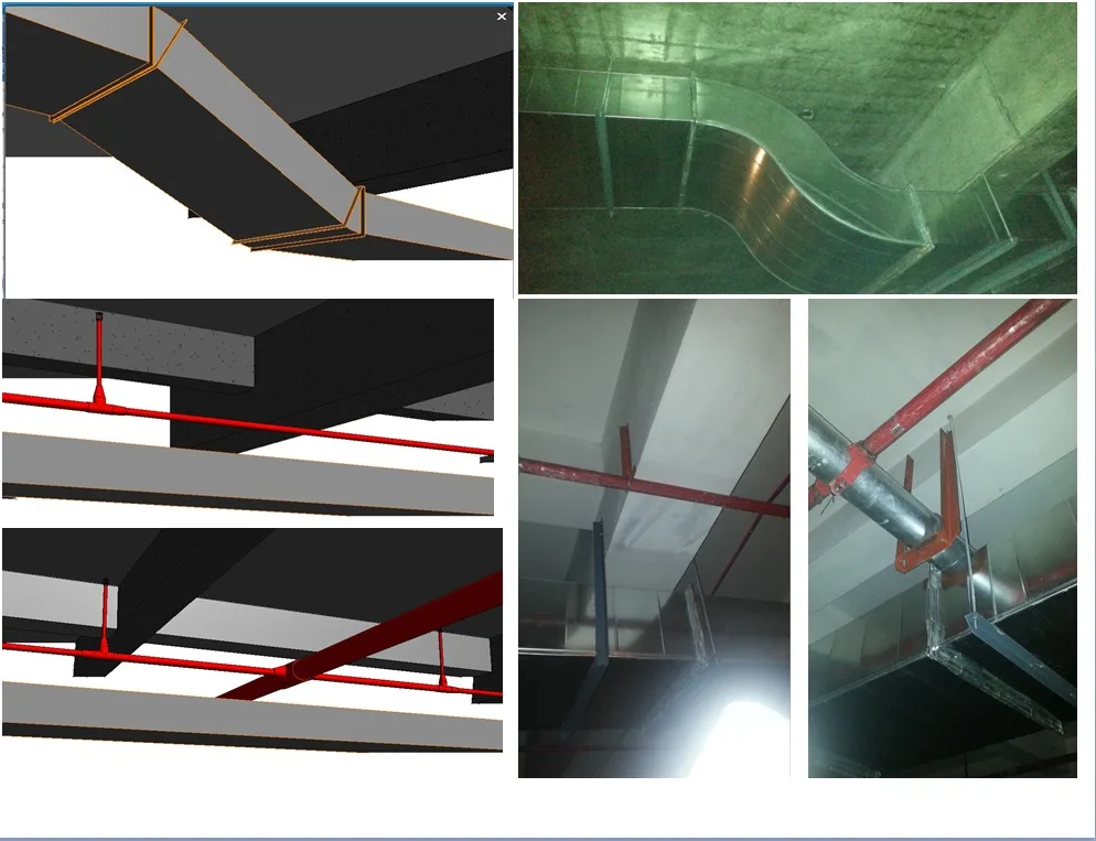
Figure 14: CAD Drawing, Model, and Construction Site – Basement Level 2
5. Summary and Lessons Learned from Using BIM Technology in the Command Center Project
The application of BIM technology in the Command Center project has yielded outstanding results. It delivered significant economic benefits to the owner and supported the country’s green construction initiatives. Moreover, it enhanced transparency throughout the construction process, reduced unnecessary expenditures, and improved owners’ visibility into capital flows.
This project has demonstrated that BIM technology integrates multidisciplinary information, simplifying and streamlining previously complex tasks. This represents a major advancement for the construction industry and points toward its future development path.


Must log in before commenting!
Sign Up