With the growing emphasis on green building concepts, lightweight prefabricated buildings have been widely promoted in China. Social and market demand continues to rise each year, with lightweight steel structures being the most commonly applied. But how can structural optimization be achieved during the construction of lightweight steel structures? And which structural design best supports green building practices? Let’s explore the analysis below.
1. Structural Background
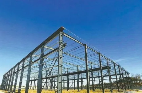
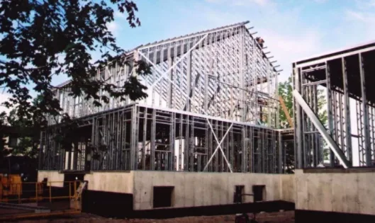
The development of lightweight steel-structured residential buildings, primarily using keel structure systems, has accelerated rapidly and become a key sector in promoting green buildings. Numerous engineering projects have been completed nationwide. According to the current GB/T 50378-2014 “Green Building Evaluation Standard,” structural optimization is explicitly recognized as an evaluation criterion. Material conservation and resource utilization are among the seven main evaluation indices, with clear scoring requirements.
Material conservation and resource utilization serve as critical evaluation factors during the structural design phase. International green building standards also emphasize these aspects. Therefore, designing innovative keel layout schemes that maximize structural efficiency is essential for advancing lightweight steel buildings. Such designs address both building energy efficiency and the broader goals of sustainable construction.
2. Structural Optimization
There is significant potential to optimize the layout of keel structures in lightweight steel buildings. The primary objective is to reduce structural stress and minimize material use. Instead of conventional vertical keel arrangements, a new truss-style keel system can be introduced, forming a more efficient structure.
Structural efficiency is evaluated by the product of rod length and stress. By comparing different keel layouts, the new truss-style system demonstrates superior stress performance and material savings. This approach aligns with green building goals, helping to reduce energy consumption and promote sustainable development.
1. Finite Element Analysis
Using ABAQUS finite element software, analyses were conducted on walls measuring 2.4m × 3.0m and 4.8m × 3.0m. Various keel arrangements were tested under three load conditions: a horizontal concentrated load, a vertical uniformly distributed load, and a combination of both. The stress distribution across different truss layouts was evaluated under these scenarios.
2. Structural Efficiency Calculation
Following extensive parametric analysis, the concept of “structural efficiency” was introduced to minimize structural components while maintaining performance. This reduces material usage and aligns with green building requirements. The keel layout was optimized under varying load conditions and wall aspect ratios, quantifying the material savings achieved.
3. Operational Procedure
1. Define design limits, including material strength, deformation, and shape constraints.
2. Determine the scope of structural optimization, which can be approached through automatic or manual methods.
3. Perform cross-sectional optimization calculations.
4. Review the optimized structure by outputting design limits, initial section parameters, and calculated strength and deformation results. Determine the total weight post-optimization, and generate optimized section parameters and graphical representations. Evaluate the strength and stability of components. The software allows zooming into local areas for detailed inspection, enabling adjustments through human-machine interaction for fine-tuning parameters.
4. Conclusion
Comparing the structural efficiency ratios between the new truss-type keel layout and the traditional vertical keel layout under various wall widths and load conditions reveals that the truss system with a herringbone keel layout offers the highest efficiency and material savings.
As wall dimensions and load conditions change, the optimal keel layout varies accordingly. For walls with a width of 2.4m, the herringbone truss layout is recommended. For wider walls, the herringbone truss should be arranged based on this basic width. When horizontal loads dominate, diagonal BIM learning elements should be added to the tie rods spanning the full wall width. When vertical loads are predominant, increase the angle of the diagonal tie rods, focusing contact around the middle of the wall.
Future work will include experimental studies of the new herringbone keel truss system. Experimental data will be compared with software simulations to validate these findings.


Must log in before commenting!
Sign Up