Prefabricated construction offers numerous benefits, including convenient assembly, accelerated project timelines, minimal environmental disruption, and reliable quality control of building components. In this article, we summarize common quality issues and construction challenges encountered in prefabricated engineering. Let’s explore these aspects together.
Key Milestones
01 Structural Nodes
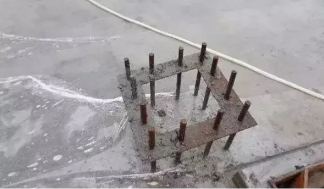
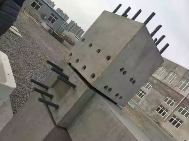
1. Column-to-Column Connection
During on-site installation, the protruding steel bars at the bottom are secured using devices such as “positioning steel plates” to ensure they align precisely with the grouting sleeves on the upper prefabricated columns. Once the cast-in-place concrete floor has been poured and cured, the upper prefabricated column is hoisted into place, and the lower steel bars are inserted into the corresponding grouting sleeves of the upper column. After temporary adjustment and fixation, grouting is performed. Prefabricated columns can take various shapes, including square or cylindrical forms, with grouting sleeve connections providing strong and effective joints.
2. Beam-to-Column Connection
In this type of connection, the lower longitudinal bars of prefabricated beams typically do not extend into the core area of the node. Instead, they overlap with steel bars from the beam end and additional reinforcement that extend into or cross the node’s core area. BIM-designed concrete is then poured to create a monolithic structure. A common method involves reserving a small U-shaped thin-walled keyway at the beam’s end. The bottom longitudinal reinforcement is cut off at the keyway’s end, allowing additional reinforcement to pass through the node’s core area and be placed inside the keyway.
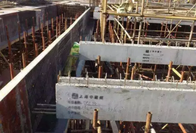
3. Primary-to-Secondary Beam Connection
Prefabricated primary-secondary beam connections often utilize either integral pouring or suspended connection methods. In most cases, a cast-in-place section is reserved at the center of the precast main beam, which contains continuous bottom reinforcement. The secondary beam’s bottom reinforcement extends beyond its end into this reserved section of the primary beam, where concrete is poured to form a continuous connection.
This reserved gap in the main beam complicates prefabrication and hoisting. Alternatively, a cast-in-place main-secondary beam connection without a gap can be employed. Anti-shear steel plates are installed at the main beam’s connection point, with short steel bars reserved to connect with the secondary beam’s lower bars. After hoisting the secondary beam, the protruding steel bars connect to the reserved short bars on the main beam via grouting sleeves.
Suspended connections typically do not connect the lower reinforcement of the secondary beam. Instead, protruding steps or steel plates (“shoulder poles”) at the beam end rest on a small gap reserved in the main beam. This setup forms a hinged node under shear loads, aligning with structural calculation assumptions.
02 Non-Structural Nodes
Wall panels serve as the enclosure structure for prefabricated concrete frames but are generally not considered structural to minimize their influence on the main structure’s stress and deformation. External wall panels designed to accommodate lateral load-induced deformation fall into rotary, translational, or fixed types.
Based on connection methods, these panels are categorized as point-hanging, line-hanging, or combined point-line hanging types.
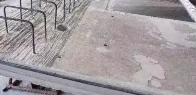
1. Point Hanging Type
This method allows external wall panels to be installed after the main structure’s completion, known as the “rear hanging method,” avoiding delays in the main structure’s progress. Installation is flexible but embedded metal parts often protrude from the floor slab, which may affect the building’s usability.
Panels connected with wire hanging often have protruding steel bars at the top.
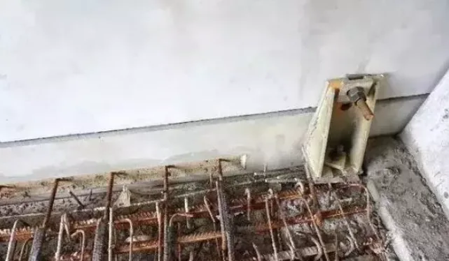
2. Wire Hanging Wall Panel
During installation, reserved steel bars are inserted into the post-pouring areas of floor slabs or frame beams, establishing a “wet connection” between the external wall panel and the main structure through these bars and poured concrete. This method offers reliable connection performance and strong overall integrity but requires simultaneous installation with the main structure’s floor and follows a fixed construction sequence. Combining point and line hanging creates a “points and lines” connection method.
3. Combined Point and Line Connections
Wall panels connected this way have distributed reserved steel bars alongside embedded metal parts. During installation, a localized post-pouring area is reserved at the corresponding location in the main structure. Panels are initially fixed with embedded metal parts, then the reserved steel bars are inserted into the post-pouring area. Concrete is poured to complete the connection. This approach combines the “post-installation” flexibility of point hanging with the “wet connection” integrity of line hanging, although the installation process is more involved.
Key Construction Points
01 Layout Planning
(1) Use 20mm thick steel plates for on-site hardening, covering the base of the outer frame of the conventional material yard (including steel pipes, supports, lifting equipment, steel molds, etc.) and vehicle pathways. Steel plates facilitate turnover and support environmental protection and energy conservation.
(2) Vehicle access routes must allow simultaneous entry and exit to prevent delays in lifting and connection due to traffic congestion.
(3) The number of tower cranes should be determined by the number of components—more cranes shorten construction time. Crane type and placement depend on component weight and lifting range, prioritizing proximity to the most complex or heaviest components.
02 Preparation Before Lifting
(1) Organize and install lifting equipment tailored to the size and form of components to save time and ensure safety.
(2) Load components in lifting sequence order to avoid onsite transport delays.
(3) Upon arrival, mark each component with serial numbers matching the lifting plan and drawings to assist workers and reduce errors.
(4) Pre-position control lines on components to reduce lifting and adjustment time and improve quality control.
(5) Install adjustment tool embedded parts on walls before lifting to reduce time and facilitate quality checks.
(6) Complete the lower support system and accurately adjust support elevations before lifting.
(7) Measure and correct column top elevations before lifting beams to ensure alignment with beam bottom elevations.
03 Lifting Process
(1) If a component’s top surface is uneven when lifted, adjust it to be level before positioning to aid alignment and placement.
(2) After removing column formwork, immediately check and adjust steel bar positions to prevent conflicts with beam reinforcement.
(3) For components with varying lifting point heights (e.g., windows, balconies, stairs), connect lower points with a hoist to level and fine-tune elevation during placement.
(4) Install one column hoop reinforcement in the column’s core before lifting beams; add two hoops after beam placement but before lifting beams and walls to ensure core quality.
(5) Survey beam bottom elevations and plan lifting sequence from lowest to highest beams, especially at intersections.
(6) Tie beam reinforcement only after wall lifting to avoid obstructing wall anchorage bars.
(7) When lifting walls horizontally, attach lifting devices first, then after lowering to the ground, move devices to the top, place protective pads at the base, and rotate the wall vertically to prevent corner damage.
04 Panel Production and Installation Issues
1. Corner Board Damage
Corner boards are thin, large, and prone to corner breakage during transport and lifting. Damage often occurs due to internal folding during lifting or poor maintenance during production, leading to angle distortion. Partially cast-in-place work to increase building integrity can cause poor formwork connection, resulting in expansion and insufficient vibration.
2. Composite Panel Cracking
During transport and lifting, laminated panels may crack or fracture. Production defects include warping, missing or broken corners, exposed truss bars, and detachment of embedded parts. Causes include excessive panel spans, compression during transport, excessive deflection during lifting, uneven release agent application, and processing errors.
3. Exterior Wall Panel Insulation Damage
The insulation layer on prefabricated exterior wall panels often detaches or breaks. These “sandwich” panels consist of an exterior decorative surface, insulation layer, and structural layer. Material incompatibility can cause insulation to fall off.
05 Connection Issues with Prefabricated Components
1. Insufficient Grouting
Determining grouting completeness in longitudinal connections of prefabricated wall panels is challenging. Grouting holes may become blocked due to poor cleaning during factory production. Typically, grouting is considered complete when concrete flows out of the upper slab holes, but internal verification is difficult.
2. Sleeve Connection Misalignment
Steel bars and sleeve positions may become offset during connection, either partially (allowing limited insertion) or completely (requiring rework). Causes include small sleeve apertures, inaccurate production positioning, and on-site cutting or bending of steel bars, all of which compromise design integrity and safety.
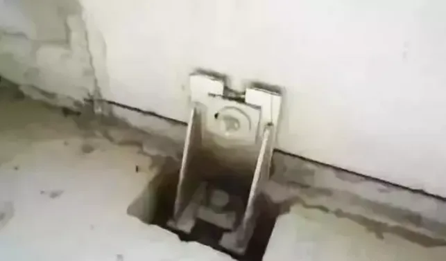
3. Pipeline and Component Embedding Problems
Pre-embedded pipelines may become blocked or detached, and their positions can shift. Obstacles during threading on-site often result from poor connection during production, concrete intrusion during vibration, and inadequate fixing within the building industrialization process. Additionally, 90° right-angle bends in pre-embedded conduits complicate on-site threading.
06 Reinforcement Positioning
(1) Reinforce all upper openings of large exterior wall formworks with mouth ridges, and have professional surveyors accurately mark steel bar positions, securing nails and wires atop the ridges.
(2) After concrete pouring and vibration, carpenters immediately pull straight lines, nail positioning tools, and make precise adjustments accordingly.
(3) Insert steel bars downward along mold hole positions after installing the positioning mold, ensuring exposed steel bars meet specifications, then verify positions again.
(4) Once concrete has set, remove and clean positioning formwork; chisel 50mm around steel reinforcement locations to facilitate fine adjustments and ensure accurate installation of prefabricated shear walls.
07 Grouting Sleeve Procedure
(1) Mix grouting material strictly following manufacturer instructions: add weighed water to a bucket, introduce two-thirds of the grouting material, stir for about two minutes, then add the remaining slurry and stir for one minute.
(2) Clean debris inside sleeves and prepare surrounding gaps on prefabricated boards. Attach the grout gun, connect to the lower hole, and begin slow grouting. When grout flows out from the upper hole, the sleeve is fully filled. Seal upper and lower holes with plugs.
(3) Clean tools immediately within 30 minutes after grouting to prevent slurry hardening and difficulty of removal.
Article source: Architectural Technology Magazine


Must log in before commenting!
Sign Up