1. Introduction
As China’s national economy advances, various industries have built a strong foundation in design technology investment. The use of computer-based 3D design technology in Chinese enterprises is now widespread. Among 3D design software, CATIA is extensively used in vehicle research and development within the rail transit sector. Urban rail transit vehicles—such as subways, light rails, and maglev trains—feature complex 3D models of the entire product. When the number of assembled parts and components reaches a substantial scale, simply opening the 3D model can max out the memory capacity of a typical 32-bit computer system, often preventing any further operations and significantly reducing design efficiency. To better address these challenges, the author has explored methodologies and specific solutions for applying CATIA, achieving positive results in practice.
2. Characteristics of 3D Design for Large-Scale Systems
For small product models, CATIA efficiently supports 3D modeling, 2D drawing, and simulation analysis. However, as the model size grows, or when collaborative design across multiple remote sites and members is required, hardware limitations can hinder performance. Challenges arise in managing design data efficiently, modifying models, and borrowing components, with processing speed becoming a critical bottleneck.
For instance, on a workstation, opening a 3D model with a data size of approximately 386MB and containing 3,296 parts—a medium-sized model—can take up to 8 minutes and consume 64.9% of system memory. Performing 2D mapping, model updates, or other operations then becomes unfeasible. Additionally, factors like the number of assembly constraints and inter-model relationships further impact processing speed, causing significant frustration for designers working with large-scale digital models.
3. Top-Down Design Approach
The overall design team defines the vehicle’s assembly structure, creates the basic framework for both the overall assembly and its subassemblies, and develops skeleton files that are distributed to subsystem designers. These skeleton files may initially be empty, representing logical relationships without containing data. Subsystem designers use the same approach to define assemblies and components within their scope, creating skeletons for important subsystem components. The detailed design work is then carried out by subsystem or component designers. The design process is illustrated in Figure 1.
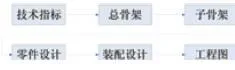
Figure 1: Design Flow Chart
(1) Obtain the overall product technical specifications from the contract or technical documents.
(2) Perform overall planning based on technical indicators, designing the framework according to relevant standards and referencing mature past products. Any borrowed elements must be properly detached.
(3) Each system designs sub-skeletons based on the overall skeleton and uses the overall skeleton solely as a design reference.
(4) Design specific parts with external associations only to the subsystem’s sub-skeleton. Reference elements from other sources are allowed but must be parameterized.
(5) Integrate designed parts into assemblies to form virtual products, then conduct analysis and inspection to refine the design.
(6) Generate 2D engineering drawings from 3D parts and components, including dimensioning, title blocks, and annotations.
4. Skeleton Design
The skeleton is the foundation of CATIA design, controlling the layout of the entire vehicle or system. It contains key geometric structures and parameter specifications critical to the vehicle’s architecture and supports the entire design and assembly process. Represented by a CATPart file, the skeleton is created and modified by the overall design lead. It includes essential elements such as vehicle reference planes (track surface, longitudinal center, vehicle distance plane, floor plane, aluminum floor plane, roof plane), vehicle contours (lines and surfaces), air conditioning reference curves, and geometric elements for each subsystem (windows, doors, HVAC platform, pantograph platform, undercarriage equipment limits, bogie). These elements serve as constraints and references for subsystem designs. The skeleton also stores global parameters like vehicle length, roof height, floor height, and bogie center distance. For complex overall designs, subsystem-specific elements that do not impact other structures can be grouped into subsystem skeletons to control and drive those parts.
Skeletons are categorized by their scope: total skeletons and sub-skeletons. The overall framework includes the vehicle body and bogie frameworks. Figure 2 illustrates an example of a car body skeleton.
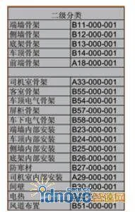
Figure 2: Classification of Secondary Sub-Skeletons
1. Skeleton Template
Figure 3 shows geometric elements of a skeleton file, and Figure 4 presents the skeleton design template structure.
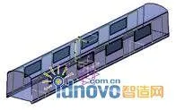
Figure 3: Geometric Elements of Skeleton
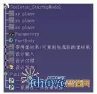
Figure 4: Structure of Skeleton Design Template
The skeleton template’s feature tree includes four sets of geometric groups with distinct purposes:
- Part Coordinate System: stores the origin coordinates; can be copied and repositioned.
- Design Inputs: stores external reference information, such as data referenced by sub-skeletons from the overall skeleton.
- Design Process: stores all results and their resolution processes.
- Design Release: contains results to be published, mirroring the design process set, providing designers with selectable elements.
2. Reference and Association Design of Skeleton
Subsystem designers open the skeleton file, copy needed geometric elements, and paste them into their own files with associative links. This approach not only provides the required geometry but also maintains associations with the original skeleton. When key parameters or contour shapes require changes, the overall design lead modifies the skeleton file, automatically updating all related subsystem structures. This ensures all referenced constraints stay consistent with the overall skeleton.
To maintain these associations and maximize modifiability, designers must follow proper procedures when creating, modifying, and referencing skeleton elements. If association errors occur, links can be disconnected. After disconnection, elements can be copied, pasted, and replaced again to re-establish associations while preserving existing design work. The CATIA file associations are managed in the SmarTeam system.
3. Precautions for Using Skeleton
(1) When using sub-skeletons, it is advisable to limit to secondary skeletons only, reducing hierarchy complexity. Skeleton information should be transmitted stepwise from the overall skeleton to sub-skeletons, then to parts, as illustrated in Figure 5.
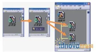
Figure 5: Correlation Between Skeleton Files
(2) Common mistakes to avoid when referencing skeleton information include:
- Do not reference information directly from the overall skeleton as shown in Figure 6.
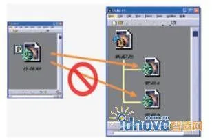
Figure 6: Incorrect Citation of the Overall Skeleton
- Avoid direct references between parts. If necessary, disconnect the resulting links, as shown in Figure 7.
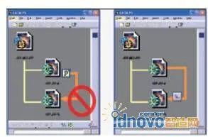
Figure 7: Incorrect References Between Parts
◎ The skeleton file should never be inserted directly into an assembly file (Figure 8). Instead, use CCP Link to copy skeleton information into part files for use.
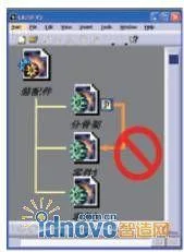
Figure 8: Incorrect Reference of Skeleton
5. Establishing Starting Templates
To meet diverse design needs, five starting template documents were developed: skeleton design template, part design template, composite material template, external component template, and assembly design template. Designers begin their work using these templates, which standardize workflows and boost efficiency.
For example, the part design template is tailored to solid parts’ structures and features. It centers on Boolean operations and includes density and center-of-gravity calculation functions, as shown in Figure 9.
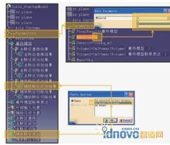
Figure 9: Part Design Template
The template’s feature tree includes:
- External Input Elements: Store information copied from skeleton files; auxiliary geometric elements store references created during modeling.
- Parameters: Store density, weight, material, and other parameters, with materials selected from dropdowns that automatically calculate related values.
- Relations: Store numerical functions and conditional logic related to mass and material.
- Final Model: Holds Boolean operation results on solid features.
- Five geometry sets—main baseline, main addition, main removal, auxiliary addition, auxiliary removal—track local feature creation, maintaining CCP Link between sub-features and Boolean results.
6. Handling Large Assemblies
Large assemblies contain vast data and multiple associations, causing slow opening, submission to 2D drawings, and sluggish inspection and analysis. Solutions include:
- Enable caching to quickly open and browse models without affecting measurements or analysis.
- Use the Associated Part function to resolve slow background processing in large assembly projections. When parts are changed, added, or deleted, the Associated Parts update synchronously.
- Selective loading of documents: load only required models when opening assemblies; for partial modifications, load only local models and then update Associated Parts.
1. Generation and Use of Associated Parts
After opening a file and switching to design mode, the Associability command in CATIA generates a multi-body part from the active assembly, as shown in Figure 10.
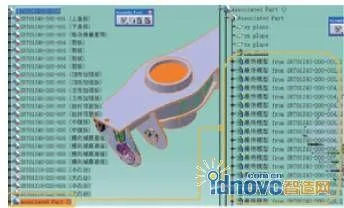
Figure 10: Result of the Associativity Command
All geometries maintain external associations with their respective part files and can be updated anytime within the assembly. When sub-parts change, the Associated Part updates synchronously. This part can be used to generate 2D drawings and serve as background data for other assembly documents.
2. Large Assembly 2D Drawing Method
For engineering drawings, selecting the Associated Part for projection (Figure 11) yields drawings with smaller file sizes and significantly faster operations compared to traditional methods.
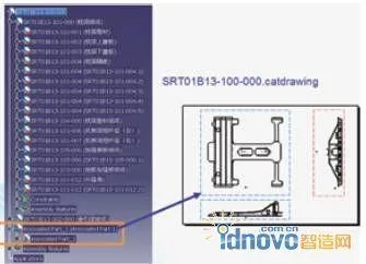
Figure 11: Generating Engineering Drawings Using Associated Parts
7. Standardization of Engineering Drawings
To standardize engineering drawings, company-specific drawing specifications were developed. By configuring Standards and GVS (Generative View Style) in CATIA, drawings conform to company requirements, creating a customized environment.
Standards cover information in 2D drawings such as drawing frames (size and perspective), dimensions (values, lines, arrows), views (annotations and outlines), text (font and size), and tolerances.
GVS settings control the visibility of elements like axes, centerlines, fillets, hidden lines, threads, 3D points, and wireframes, as well as line types, widths, and colors for various views (sections, details, etc.).
8. Application of the TubingDesign Module in Pipeline Design
Comparison of TubingDesign and Traditional Methods
To streamline pipeline design, the CATIA TubingDesign module was introduced. Traditional design involves sketching pipeline skeletons with the PartDesign menu, using rib commands to generate pipelines, and assembling components from libraries with constraints—resulting in large data and cumbersome modifications.
With TubingDesign, pipeline routing follows drawings directly. The placetubingpart command calls library attachments, placing them precisely before applying pipeline material (TubeWithBends), as shown in Figure 12.
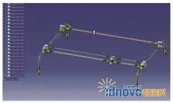
Figure 12: Generating Pipeline
Pipelines designed with this module are data-efficient, simple to design, and easy to modify, aligning with engineers’ habits. In the HD2 model, pipeline attachments are constrained and require re-adjustment after skeleton changes. In TubingDesign models, pipelines and accessories are associated; modifying pipeline direction moves accessories accordingly (Figure 13), and moving joints adjusts pipeline routing.
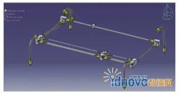
Figure 13: Modification of Pipelines or Accessories
Advantages of using TubingDesign for pipelines include:
- Simplified process without requiring sketches to construct skeletons, enabling direct pipeline creation.
- Attachments imported and positioned directly from the library using placetubingpart, without constraints.
- Customizable pipeline numbering rules.
- Pipeline classification and property assignment during environment setup, allowing direct use in design.
- Fast and convenient post-production modifications.
- Seamless integration of 2D and 3D design.
- Automatic report generation to facilitate counting pipeline and accessory types and quantities.
- Small model sizes and fast operation.
2. Management and Access of Pipeline Standard Parts Library in SmarTeam
The TubingPartsCatalog environment is parsed and saved to SmarTeam on the server, then released while retaining a local library copy. Engineers access standard parts through network file sharing rather than direct electronic warehouse access, improving design efficiency. This setup also records SmarTeam attribute information for pipeline components, simplifying PDM system management.
9. Conclusion
Following the implementation of these measures, the efficiency and quality of 3D design applications have significantly improved. Shanghai’s domestically produced A-type subway completed a 100,000-kilometer passenger operation test, meeting all technical specifications. The successful development and testing of the A-type subway within two years was achieved through advanced design methods, integration of industry, academia, research, and application by the Urban Rail Transit Branch of the Transportation Commission and local governments, leveraging diverse social resources, and pioneering the practical application of domestic core technologies in major projects. Our company has independently innovated and developed solutions based on thorough user needs analysis, forging a new path in the design and manufacturing of major equipment. This progress positively contributes to the healthy development of the urban rail transit industry.
Author: Shanghai Rail Transit Equipment Development Co., Ltd. Chen Wenhong, Yan Xiaoming, Zhou Hong
Shanghai Jiangda Technology Development Co., Ltd. Lu Guanglin
Source: CAD/CAM and Manufacturing Informatization


Must log in before commenting!
Sign Up