The wave of information technology is transforming industries worldwide. In architecture, various 3D digital design software are playing an increasingly vital role in the creative process of architects, enabling them to turn imaginative concepts into tangible reality. Leading architects both in China and abroad have successfully integrated software with human intelligence to produce unprecedented architectural forms and spatial experiences. However, traditional social concepts, industry systems, design methods, and construction techniques still restrict architects’ exploration—especially in the design and construction of large-scale buildings.
With support from the Shanghai Autodesk China Research Institute, Autodesk Revit 2010 beta software was successfully applied to the construction drawing design of the Mogao Grottoes of Dunhuang Tourist Center, offering architects a new experience. The lessons learned from this process are worth sharing.
Located on the edge of the Gobi Desert and facing its vast expanse, the Mogao Grottoes Tourist Center rises naturally from the earth, resembling wind-swept sand dunes. The building features several sets of free-form roofs that intertwine, twist, and separate—some even punctuated by openings, reminiscent of an hourglass. The main indoor public space exposes curved cross-shaped beams, similar to a coffered grid in a cave. Facade windows are inspired by caves carved into cliffs, with curved chamfered niches built into double-layered walls. These complex forms give the building its distinctive appearance, but also pose significant challenges for construction drawing design.
Given cost limitations and local construction techniques, cast-in-place reinforced concrete was chosen over steel as the main structural material. Thus, precise positioning of three-dimensional curved concrete forms became the core issue to solve. Questions such as how to model, locate, cut sections, produce detailed node drawings, and ensure practical guidance for future construction became central to the process, diluting the initial creative passion and requiring step-by-step resolution.
3D Modeling
3D modeling was the most critical task in this construction drawing design. We sought to use Revit to accurately describe three-dimensional shapes and spaces, converting them into two-dimensional graphics for precise positioning and leveraging BIM’s advantages for efficiency, modification, and reduced workload.
The work approach was clarified by breaking down complex tasks into manageable work packages based on a unified logical structure, then refining these into simple tasks and standardizing actions for quality completion. The results were combined in reverse, following the logical structure to reach a solution.
Specifically, the process included the following steps:
- Referencing the size of concrete formwork in general construction, a 2m × 2m grid axis was used as the basic positioning scale for the entire building plan and space.
- Separating the vertical walls from the curved roofs, with two team members responsible for each.
- Further decomposing the curved roofs according to certain rules, modeling them individually, and then reassembling them to complete the overall model.
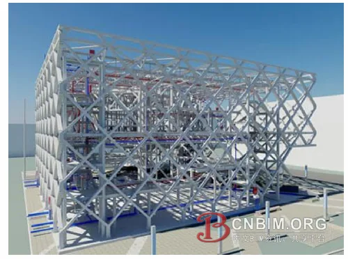
The complex surface model is fully broken down into basic unit components (Image source: Baidu)
Curved Roofs and Three-Dimensional Curved Beams
We first decomposed the working model. The longer roof was divided into two parts based on structural deformation joints, forming east and west zones. Each zone was then further broken down into individual curved roofs based on their shapes. Finally, each independent curved roof was disassembled into basic structural components—main beams, secondary beams, slabs, parapets, and overhead roof panels. In this way, the complex surface model was thoroughly broken down into basic unit components.
After decomposing the model, we defined and numbered the basic unit components into zones. This numbering provided unique spatial identification for each element, facilitating future inspection and modification. All constituent elements were listed in a comprehensive table, showing the person in charge, completion level, regional location, and difficulty. Each team member had a partition combination map, quantifying the workload, module combinations, progress, missing areas, problem spots, estimated completion time, and more. This method also reduced the intimidation of facing the overall complex form, allowing focus on creating components of varying difficulty. If a unit couldn’t be further decomposed (such as cross beams and funnels), the difficult modeling task was transferred to the Autodesk technical department, or even to Autodesk’s US headquarters if necessary. Task splitting facilitated work outsourcing.
Basic components were then created based on the partition map. Due to time constraints, after brief training with Autodesk technicians, our team had to learn on the job. The steps were:
- Cut and depict cross-sections from the scheme model.
- Produce component surfaces based on the section and component number.
- Import surfaces into the project environment and position them according to the unified coordinate grid.
- Assign properties such as beams, slabs, and columns to each component, and attach walls to roofs.
This process was repeated extensively, as the building’s free form resulted in no repetitive components, making the number of basic units extremely large and the workload heavy. Significant difficulties were encountered, especially with the cross-shaped beam on the reception hall roof, the “funnel” in the courtyard, and the curved beam in the space.
For the cross-shaped beam, we worked on solving torn surfaces, maintaining consistent curvature at contact points, applying UV lines for grid division, creating family files, and applying them to surfaces. Creating funnels involved decomposing and building surfaces with different curvatures, assigning family file modules to surfaces, and ensuring smooth connections. Spatial curved beams were relatively easier, as they relied on the curved roofs. The elevation of the beam top matched the roof top, allowing extraction of roof components. The centerline was found in the plane, with column midpoints as endpoints. The beam projection was determined from spatial endpoints, connecting continuous points in the spatial plane to generate multiple spatial lines. Using the structural height, the actual beam height was copied along the z-axis, and the wireframe enclosed by the two lines was connected to produce the central section. This was imported into the Revit model and assigned beam thickness, thus generating the spatial curved beam.
Walls, Stairs, and Windows
Revit presents few obstacles when modeling regular geometries, and its component library is quite comprehensive. Parameters enable easy modification of wall height and thickness, and allow for extension and chamfering. Stairs have detailed parameter settings, making steps, railings, and handrails easy to build. The main difficulty was creating niches and windows with cave-like curved chamfers, which required specialized family files. Once completed, these could be inserted into walls at various positions and heights, with size and proportions easily adjusted via parameters.
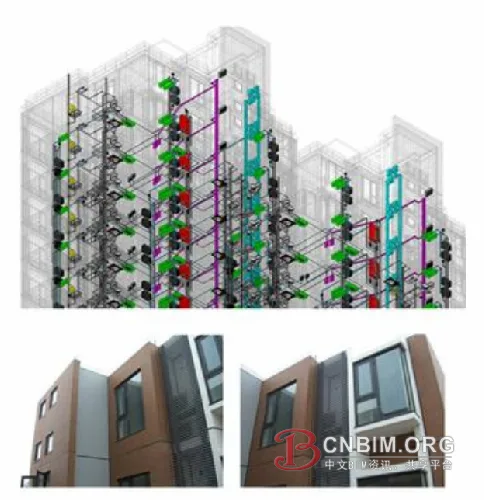
The finished effect naturally meets the design requirements (Image source: Baidu)
Positioning
The spatial positioning of curved roof panels, curved beams, and cross-sections was ultimately not resolved within Revit. Rhino, combined with Grasshopper scripts, was used to complete the final spatial positioning. The key was Grasshopper scripts, with calculations depending on the type of structural component. Scripts were arranged first, then used to calculate the three-dimensional positioning for structural drawings.
Steps for positioning:
- Extract structural components needing positioning in Revit and export as CAD files.
- Import CAD files into Rhino and calculate spatial positioning heights using Grasshopper scripts.
- Export organized CAD files from Rhino and submit to the structural department.
All plane positioning was based on the 2m × 2m grid, forming a 2m × 2m × 2m spatial grid coordinate system for the entire building. Structural components, such as irregular roof panels and curved beams, were placed in this spatial grid, with positioning point coordinates in the format (x, y, z). The x and y directions have 2m spacing, while the z height is calculated in Grasshopper. Positioning accuracy depends on grid size—the smaller the unit, the more precise. More positioning points are especially important for complex shapes, facilitating construction and ensuring the effect matches design requirements.
Generation of 2D Drawings
In traditional two-dimensional design, plan, elevation, and section views are drawn separately. Drawing a section requires rotating and aligning the plan, which is complicated for buildings with many floors and complex spaces, often leading to errors. The biggest frustration occurs when the plan changes after drawings are nearly complete, forcing extensive realignment and modification, including annotations and node details.
In Revit, all plans, elevations, sections, detailed drawings, and dimension annotations are linked to the 3D model. Any model modification automatically updates all drawings, saving time, improving efficiency, and eliminating worries about missed changes. For this project, the curved roof’s diverse variations meant that cross-sections at any point differed, and exact cut locations could not be determined in advance. Revit’s associated function proved highly accurate and real-time. Necessary settings for association enabled confident modifications to the model.
Unfortunately, due to different properties among model components, such as roof panels and walls, chamfering and intersection were not well integrated, causing generated profiles to fall short of drawing standards. Also, the software’s localization does not match traditional expression habits. Ultimately, drawings were reorganized and output in CAD.
Advantages and Disadvantages of Revit Software
Revit offers powerful functionality, an intuitive interface, and collaborative design. It provides a platform for multiple professions to collaborate in 3D design, which has great potential. However, due to a significant gap between Chinese market requirements and the software’s design, only the architecture major currently uses it, as basic needs for other disciplines are not yet met.
BIM is the core purpose of Autodesk’s creation of Revit, representing a revolution compared to 2D design. It aims to consolidate all building-related information in one document—including architecture, structure, water, heating, and electricity—which can be modified and adjusted at any phase, and kept updated. Traditional separation between blueprints and negotiation can be integrated. Renovation projects will use the latest drawings as the basis, avoiding time-consuming checks of old drawings and negotiation sheets—a significant advantage for all related industries.
To achieve this, the BIM model must include all information, requiring designers of all disciplines to express every detail. During construction, any negotiation should be modified within the same model.
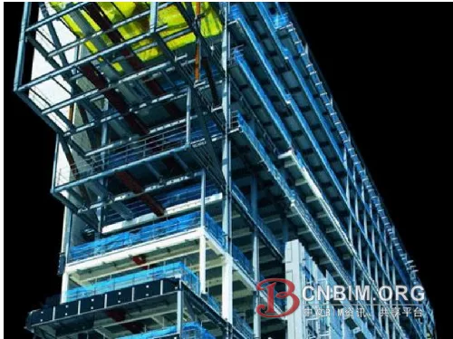
Revit provides a collaborative platform for various professions (Image source: Baidu)
For construction drawing design, 3D models can be associated with all plan, elevation, and section drawings, preventing errors from isolated changes and greatly improving efficiency. This is a major advantage of Revit as a 3D design software. It has strong curve modeling capability and can generate complex shapes through method exploration, but its surface modeling still needs improvement. In terms of parametric design, Revit allows easy adjustment of building component dimensions and control of local components via family files. For simple-shaped buildings, its performance is strong.
Based on this project, converting a 3D model into a 2D drawing reveals a fundamental issue—the localization of construction drawing design for the Chinese market. The software should adapt to national standards (calculation and drawing standards) and align with engineers’ drawing habits. Traditional drafting standards have been used by engineers and construction units for years. As an external version of Revit, there are many areas needing redevelopment for China’s situation. We recommend that Autodesk China Research Institute address this issue in the next stage.
Source: Design and Research
Authors: Wu Bin, Zhao Xiaogang, Zhang Rubing


Must log in before commenting!
Sign Up