Introduction
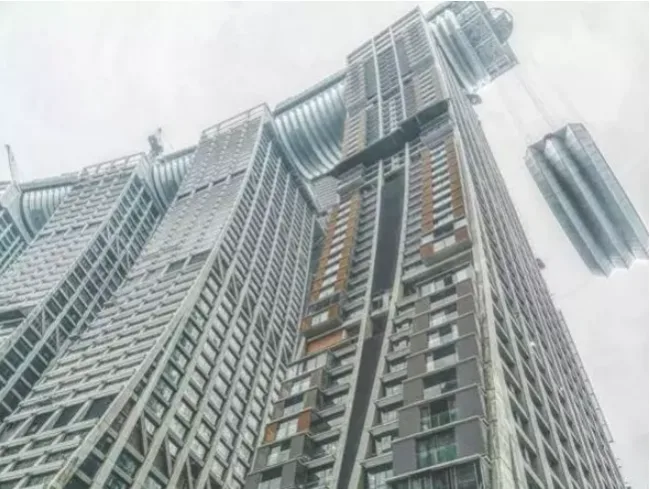
With the growing use of complex, large-span corridor structures as architectural highlights in super high-rise buildings, the challenges associated with their construction have significantly increased. To guarantee quality, safety, efficiency, and cost-effectiveness, meticulous construction design and thorough technical analysis are essential throughout the high-altitude corridor construction process.

Steel Structure Corridor Hoisting
01. Lifting Analysis
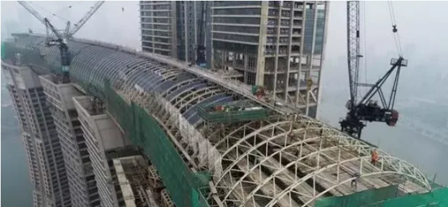
(1) The single truss of the steel structure corridor is heavy and installed at great heights. When direct high-altitude lifting by tower crane is not feasible, reinforcing the basement roof structure and assembling on the ground is an effective alternative.
(2) The corridor’s overall lifting height approaches 100 meters, involving many uncertainties. Accurate measurements and computer simulations are employed to ensure smooth execution.
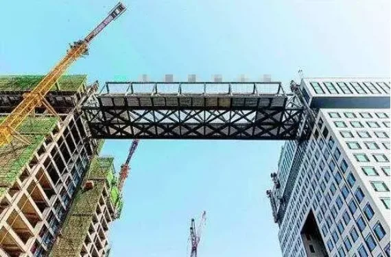
(3) With three floors in the steel structure corridor, the numerous high-altitude interfaces increase installation complexity. The main truss is used for direct interface docking, while other components are installed after docking completion.
(4) The towers flanking the corridor differ in height and experience uneven settlement, complicating stress and strain control. A staged connection approach is adopted, with final welding performed once settlement stabilizes.
(5) As an irregular structure with a challenging center of gravity, force calculations and synchronous lifting are complex. Using SAP2000 for structural simulation allows computer-controlled synchronous lifting.
02. Construction of Lifting Devices
(1) Based on design drawings, detailed prototypes are created, reviewed, and then developed into BIM learning templates. These templates help verify and adjust the actual site conditions.
(2) The four column corners are wrapped with L100 × 10 angle steel, leveled with steel plates to evenly distribute stress, and further reinforced with 100 × 10 steel strips. Support steel plate sizes are determined based on lifting rod forces.
(3) Pole components are fabricated according to the prototypes, ensuring proper dimensions and minimizing waste.
(4) Existing scaffolding is utilized for installation in coordination with scaffolders. Obstructive scaffolding components are removed during installation. Tower cranes lift the components in sequence: first, the main derrick mast HN300; then the lower diagonal brace steel pipe; and finally, the upper tie rod 2 [14 channel steel]. Angles must be accurate, and contact surfaces straight throughout installation.
(5) One boom is fabricated and inspected first. After passing inspection, the remaining booms are produced.
03. Lifting Measures
Given the corridor’s height—nearly 100 meters above ground—erecting support frames from the skirt roof risks instability. Selecting a plan that avoids complicated or costly options is critical. The chosen construction method must be safe, reliable, technically sound, and economically reasonable.
The hoisting process allows adjustment of secondary beam spacing, combining prefabrication and integral pouring. This eliminates the need for small trusses to support formwork and scaffolding, preserving floor slab integrity. Reduced spacing and cross-section of secondary beams lower lifting weight, enabling tower cranes to manage the load. If the I-beam’s bearing capacity is insufficient, two diagonal braces are added mid-span to convert single-span capacity into a three-span bearing capacity, enhancing strength.
Installation and Construction of the Corridor
01. Main Steel Beam Hoisting
The steel frame corridor is divided into two beams, lifted separately and positioned accordingly. Temporary reinforcements like round wooden poles or blocks are tied to the beams to prevent damage. Torn cloth is placed beneath the ties to protect the paint finish. To avoid excessive swaying during lifting, slip or stabilizing ropes are secured at both ends and gradually relaxed as the beam is lifted to maintain alignment.
02. Construction of Operating Platform
(1) To support fixation during lifting, 2-meter-wide cantilever scaffold platforms are erected at both ends of the corridor along the building’s edge. Scaffold pole spacing meets engineering requirements longitudinally and transversely, and platforms are positioned according to elevation plans.
(2) Scaffolding attached to the wall is secured to structural columns and tied at each step. After lifting both steel beams, additional scaffolding is installed beneath them to facilitate welding and connection of the secondary beams.
03. Steel Structure Welding
(1) Both sides of the profiled steel plate require 15mm diameter fusion welds fixed to the steel beam, spaced approximately every 30cm. Welding must penetrate the plate and fuse well with the beam material. If bolts pass through the plate and beam, they can substitute some welds; however, after positioning the plate, welding should still follow these principles, with weld diameters adjusted to 8mm or greater.
(2) Welding applies not only at the profiled steel plate’s supporting beams but also to secondary beams spanning between them.
(3) If welding studs burn through or loosen the plate due to excessive current, additional welds should be added adjacent to the studs.
04. Specific Construction Points for Each Process
1. I-beam Fabrication
I-beams are welded from 10mm thick A3 steel plates, with web plate thickness adjusted as needed for concentrated loads. Joint welds are positioned at one-third of the beam’s length, where bending moments and shear forces are lower to minimize impact on bearing capacity. Symmetrical welding reduces deformation, and flat welding ensures weld height and quality. Every welding phase strictly follows drawings and specifications. Careful fabrication minimizes the need for high-altitude work on attached components.
2. I-beam Hoisting
Concrete floors are pre-embedded with steel plates and lattice columns for I-beam placement. When placing lattice columns, precise control of axis, elevation, and verticality is essential. I-beam formwork is installed based on concrete pouring conditions.
I-beams are lifted using tower cranes with a two-point lifting method. Steel wire ropes must be equal in length and smoothly lifted from pre-made lifting rings. One end is secured to the embedded steel plate, the other to the lattice column, then welded firmly by electric welding after inspection.
3. Installation of Diagonal Pull Rods
Once concrete pouring is complete and corridor construction begins, 28mm diameter steel bar diagonal braces are installed first. Welding length on steel plates exceeds 30cm, with double-sided welds spaced every 8cm. Braces must be perfectly straight and free of bends.
4. Prefabricated Concrete Secondary Beam Fabrication and Hoisting
Secondary beams are prefabricated to strict dimensional requirements. After diagonal brace welding, prefabricated beams are only lifted when concrete strength reaches 100%. Tower cranes use a two-point lifting method with uniform-length steel wire ropes, smoothly lifting and placing beams on I-beam supports. After verifying, beams are electrically welded to ribbed plates. Horizontal tie rods are installed simultaneously from both sides toward the center. Continuous checks correct any lateral bending of steel beams. Each prefabricated secondary beam installation is supported by a scaffold section.
Common Issues and Their Control
01. Welding Deformation of Components
(1) Design welds symmetrically or use intermittent welding to minimize both number and size, reducing deformation.
(2) Use tire fixture prefabrication fixation to prevent deformation during welding; residual stresses are removed through shot blasting.
(3) Preheat the entire assembly before welding and conduct post-weld heat treatment to further reduce deformation.
(4) Implement anti-deformation control welding with accurately calculated and empirically verified quantities.
(5) Prefer high-energy density welding methods like carbon dioxide gas shielded welding and submerged arc automatic welding over manual arc welding.
(6) Use correct welding sequences and processes: symmetrical welding for H-beams; transverse seams welded before longitudinal for crisscross components; and techniques like reverse segmented or skip welding for long seams.
(7) For high-stress T-joints or cross joints, bevel welds reduce weld metal volume and deformation compared to fillet welds while maintaining strength.
02. Weld Slag Inclusion, Incomplete Penetration, and Undercutting
(1) Ensure the welded workpiece is tightly secured to the pad. Use 4mm and 3.2mm diameter welding rods as bases, maintaining gaps no larger than 8mm and 6mm respectively.
(2) Clean and properly overlap coatings when breaking arcs or changing rods. Optimize welding parameters, sequences, and techniques through pre-welding experiments.
(3) Preheat adequately and maintain proper temperature control. Dry welding rods at 300°C for 2 hours to prevent gasification from surface chemicals.
(4) Maintain welding machine secondary no-load voltage above 80V to ensure sufficient melting power. Adjust final weld current to 120A and allow a 15-minute cooldown before welding.
(5) Pass the welding arc quickly and carefully to avoid undercutting.
(6) Match weldment materials accurately to welding rod models.
03. Displacement of Steel Beams or Installation Holes
(1) Before pouring foundation concrete, position pre-embedded supports within rigid frames to prevent displacement from vibrations.
(2) Enlarge reserved holes for pre-embedded brackets to verify positions. Measure and confirm axis alignment.
04. Insufficient Tightening Torque of High-Strength Bolts
(1) Calibrate torque wrenches before use, ensuring deviations remain within 5%.
(2) Repair bolt holes with scrapers if misaligned to allow bolt insertion.
(3) Tighten bolts symmetrically from the center outward in two stages: initial tightening at ~50% of final torque, followed by final tightening. Mark and record each tightening step to avoid omissions.
(4) Keep fitting surfaces clean and free of debris.
(5) Assemble screws, nuts, and washers correctly and use them together.
Article source: Architectural Technology Magazine


Must log in before commenting!
Sign Up