1. Introduction
Today, the discussion around BIM technology is not about whether to adopt it, but rather how to implement it efficiently and transition smoothly. Throughout our experience with applying and promoting BIM, we have identified several common misconceptions:
- Misconception 1: BIM is viewed as a high-end technology. In reality, BIM is destined to become a standard design technology and will be a necessary qualification for all designers and engineers.
- Misconception 2: BIM is considered very difficult to learn. While BIM is more complex than 2D design tools like AutoCAD, its challenge lies in learning the rules and legal requirements embedded in every step. Mastery requires more time and effort, but not advanced technical skills or strong computing backgrounds.
- Misconception 3: BIM can be quickly mastered. This belief often leads to frustration and abandonment during implementation. Contrary to claims by software vendors and “crash course” tutorials, true proficiency in BIM takes months, not weeks, and requires a supportive BIM environment.
- Misconception 4: BIM dramatically increases design institute productivity. BIM improves overall efficiency across design, construction, and operation. While it may increase information input in the design phase, these efforts are offset by enhanced collaboration, offering long-term competitive advantages.
- Misconception 5: Having a dedicated BIM team is enough. In fact, only organizations that fully adopt BIM will remain competitive in the future.
This article uses a pipeline integration project at the Architectural Design and Research Institute of Tsinghua University to illustrate the differences between BIM and conventional design methods, as well as strategies for integration and transition.
2. Project Overview
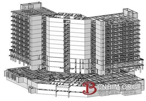
The BIM pipeline integration project is part of the outpatient comprehensive building in the first phase of Tsinghua University’s new hospital. The site covers 10.14 hectares with a total construction area of 94,510 square meters. The building has 2 underground and 13 above-ground floors, reaching a height of 63.45 meters as a high-rise structure. The complex layout and dense, diverse pipelines, with varying floor heights and unique standard floors from basement level 2 up to floor 5, make this project particularly challenging for traditional 2D design methods.
In this context, the BIM center and project designers collaborated using Revit MEP for 3D pipeline layout. This approach enabled them to adjust pipelines in 3D, avoid collisions, maximize usable room height, and conduct effective BIM training and promotion.
3. Overall Organization
The project combined traditional and BIM design, dividing responsibilities between a design team and a BIM team. These teams collaborated throughout the project. The BIM team primarily used Revit Architecture and MEP from the 2011 series, supplemented by tools like Autodesk Design Review 2011.
4. Team Collaboration Model
The collaboration between the BIM and design teams occurred in two stages. Initially, the teams operated independently, as illustrated below:
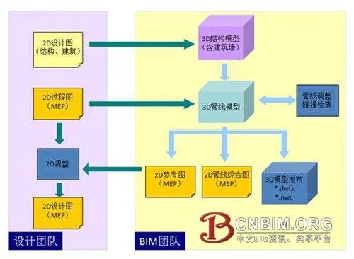
Relatively independent collaboration between design and BIM teams
In this stage, the design team used traditional 2D methods. The BIM team created a 3D BIM model based on their drawings, then both teams performed collision checks and pipeline adjustments using the 3D model. After adjustments, a 2D reference diagram was automatically generated, allowing the design team to finalize the design documents. The BIM team also produced a 3D release file to replace the conventional 2D pipeline synthesis diagram, viewable with Autodesk Design Review 2011.
This approach required minimal BIM training for the design team and enabled successful pipeline layout and adjustment for a standard floor. The process allowed the design team to experience BIM’s advantages firsthand, deepening their understanding and preparing for further BIM training.
Next, the BIM center provided practical, project-oriented BIM training, allowing designers to quickly begin BIM design with support. The BIM center also managed equipment setup, software installation, network configuration, system templates, family development, standard customization, and collaborative assistance. Without BIM team support, these tasks would consume significant time and energy from the design team, highlighting why BIM adoption has historically been challenging.
Once the design team transitioned to BIM, the collaboration model shifted, with the BIM center focusing on technical support. Direct BIM adoption improved efficiency by eliminating redundant data entry and result verification.
5. Collaborative Work
BIM collaborative design fundamentally differs from 2D CAD collaboration, which relies on network communication. In BIM, collaboration is integral to the design method itself. Instead of referencing files, all team members build and manage a shared virtual model in real time, including buildings, structures, equipment, and pipelines. Immediate visibility and conflict detection are possible, enabling instant engineering discussions.
Revit’s central file represents this virtual model, facilitating easy collaborative work, as shown below:
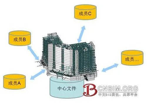
Technical collaboration in Revit is straightforward
Without collaboration, BIM cannot function. While Revit’s technical collaboration is easy to learn, it requires a shift in design mentality from individual work to coordinated teamwork. Good project planning and management are essential. In Revit, each work unit is called a Workset. Well-designed Worksets ensure logical project structure, clear organization, and enable various advanced functions.
6. Structural Model Creation
For pipeline collision inspection, a structural model is required, but building walls are included due to their impact on pipeline layout.
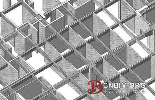
Internal structure including building walls
For high-rise buildings, dividing Worksets by floor is effective. Although Revit uses the concept of layers, it doesn’t directly control layer display. Worksets serve as an operational unit for collaborative work and are the most effective tool for controlling display. In the model below, the middle two floors and each floor slab are hidden using Worksets:
Hidden structure of middle floors and slabs via Worksets
Unlike AutoCAD, Revit does not use “layers” but instead categorizes and controls components by function and type. Floors, beams, and columns are managed directly through Revit’s display controls. For custom criteria, such as beams of certain heights, Revit offers filters for classification and display control. While Revit provides powerful categorization methods, its customization is less intuitive for beginners compared to layers.
7. Linking Structural Models
Pipe modeling is not done directly in the structural model. Revit recommends keeping structural and MEP models independent, using linking for reference. In this hospital project, the structural model was linked to the MEP model, ensuring structural updates are automatically reflected in the MEP model.
Revit 2011 introduced the ability to control Workset display in linked models within the main model, allowing selective opening of structural layers for reference. Previously, this required more cumbersome processes.
8. MEP Model Layout and Adjustment
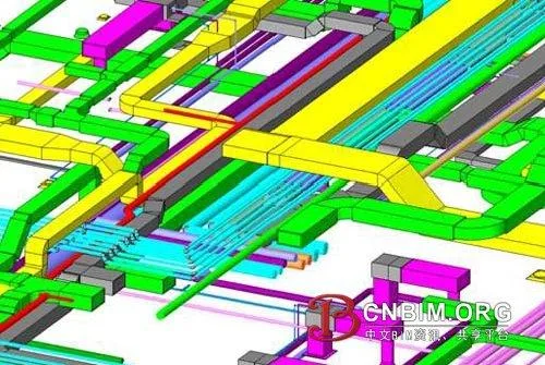
Due to the complex structure, Worksets were divided by both floor and pipeline type. The diagram below shows the division of Worksets at the fourth level, highlighting pipeline complexity and BIM’s focus on management and coordination:
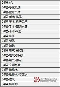
Pipeline arrangement and adjustment in Revit
Arranging and adjusting pipelines in Revit requires understanding the rules and priorities for layout. Generally, gravity-driven and sloping pipes (e.g., sewage, waste, condensate, steam, rainwater pipes) are prioritized due to their slope requirements for smooth flow. Improper layout can affect ceiling heights.
Air ducts should be placed as close to the top as possible, and high-pressure sloping ducts should avoid tight spaces. Other pipes are prioritized by slope, pressure, and flexibility—rigid pipes take precedence over flexible ones, and smaller pipes yield to larger ones. Flexible pipes, like medical gas or ventilation, are lower priority, but care must be taken to avoid U-bends that could cause blockages.
Hot water, air conditioning, and other pipes should be installed at a slope, but long runs require vertical space and vent valves at bends (fan coil units can serve as vent valves). Fire pipes were arranged through beams to save height, and for tight vertical spaces, parallel sewage pipes were used to avoid intersections, merging them in pipe wells to reduce height requirements.
Underground structure and pipeline layout
Revit’s collision checking tool helps detect conflicts between parts or the entire building. Collisions can be selectively checked (e.g., ducts vs. structure, ducts vs. ducts, sewage vs. ducts). However, Revit’s collision detection is basic and only finds hard collisions; more complex checks, such as spacing, require exporting to Navisworks.
9. Difficulties and Shortcomings
The main challenge in implementing BIM is establishing the initial environment:
- Mindset shift: Transitioning from 2D to BIM design is difficult and requires significant adjustment.
- Localization: Revit’s localization needs improvement. We produced many custom families and templates to match Chinese standards. Domestic manufacturers have not provided product families like foreign counterparts, impacting cost estimation, operational management, and model accuracy. For BIM to be effective throughout a building’s lifecycle, this must be addressed.
- Software efficiency: Revit 2011 improved efficiency and reduced hardware demands, but strong hardware is still needed. The center uses advanced graphics workstations and Windows 7 64-bit OS to run Revit. High implementation costs of software, hardware, talent, team building, management, and training remain barriers.
- Training costs: Time and financial investments in training must be carefully managed to avoid disrupting production.
In summary, the high initial costs—including software, hardware, talent, team building, management, and training—are major obstacles to BIM implementation.
Source: “Architectural Techniques” by Chen Yujun, Architectural Design and Research Institute of Tsinghua University


Must log in before commenting!
Sign Up