Prefabricated small box girders have rapidly advanced and become widely adopted both domestically and internationally, thanks to their excellent torsional and bending strength, cost efficiency, and fast construction speed. Today, let’s explore how to standardize the construction process of prefabricated small box girders.
1. Construction Methods and Process Flow
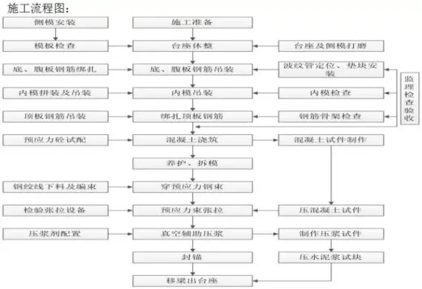
1.1 Process Principles and Workflow
The prefabrication of box girders is carried out vertically using specialized molds constructed on-site.
First, the steel reinforcement framework is fabricated and secured onto the tire mold, with corrugated pipes installed to create the prestressed tendon ducts. Next, dedicated steel formwork for the beam is assembled, followed by concrete pouring and curing. Once the concrete attains sufficient strength, the side formwork is removed, and curing continues. After reaching the required design strength, prestressed cables are threaded through the ducts, tensioned, and anchored sequentially. Finally, grouting and anchoring complete the prefabrication process.
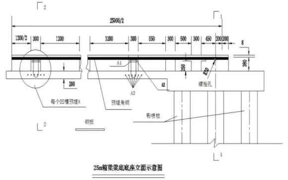
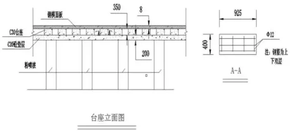
1.2 Beam Pedestal Setup
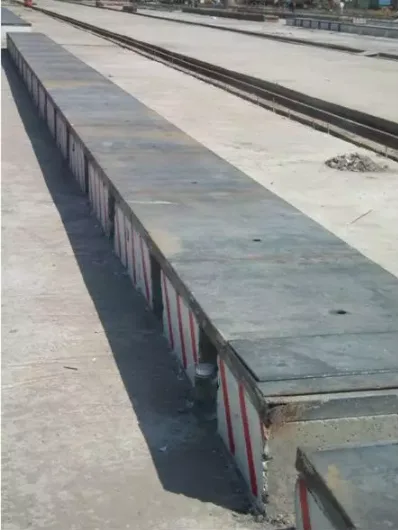
The expanded foundations at both ends of the 25-meter box girder base measure 300 × 300 × 50 cm, reinforced with two layers of steel mesh due to the concentrated forces after tensioning. The middle section features a 20 cm thick C25 foundation concrete slab with four Φ12 full-length steel bars embedded.
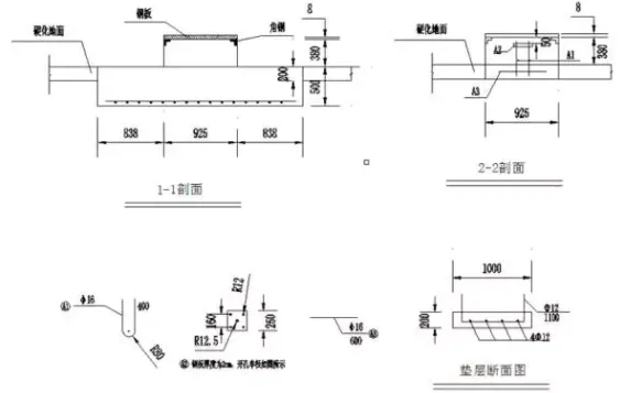
The box girder base length is set at 25.4 meters, with longitudinal and transverse spacing arranged per station design drawings. The base stands 38 cm above the hardened concrete surface, including steel panel thickness. Load-bearing concrete seats measure 92.5 × 50 × 30 cm with 50 cm spacing to facilitate installation of locking foot screws and internal formwork pull rods.
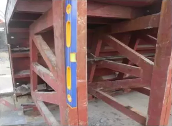
The arching resistance value of the base is calculated using a quadratic parabola. Embedded angle steel lines are checked and adjusted for type, width, weld points, and arching resistance at each control point. After compliance, steel bar diagonal and flat braces are welded.
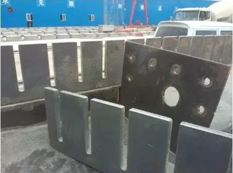
Templates are installed around and at both ends of the base pier, with detachable steel panels positioned 60–110 cm from the beam end to ease installation and hoisting of steel wire ropes. After reinforcing the templates, C30 base concrete is poured, the surface smoothed and grouted.
When the concrete reaches adequate strength, a handheld grinder smooths the surface, inspected with a ruler. Finally, manufacturer-processed steel panels are welded onto embedded angle steel according to numbering. Joints are cleaned with a curing agent mixed with atomic powder, and 4 mm anti-slurry rubber tape is applied on both sides with strong adhesive.
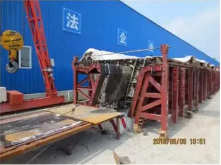
1.3 Installation of Prefabricated Small Box Girder Formwork
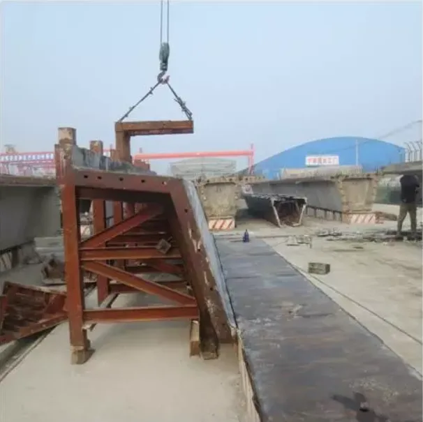
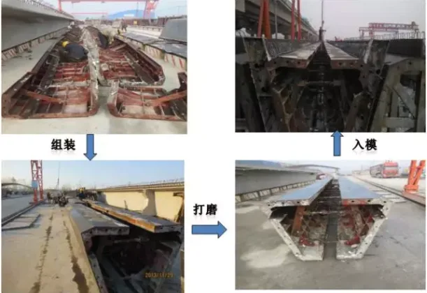
1.3.1 Due to the integrated lifting and shaping of the steel reinforcement framework, the side formwork is pre-installed and connected to the bottom formwork. A 10-ton gantry crane is used to assemble and connect sections with the bottom formwork, minimizing joint misalignment and ensuring the beam’s appearance quality.
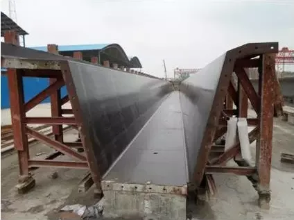
1.3.2 When setting the bottom mold, No. 5 channel steel serves as the pedestal edge with the angle steel groove facing inward, and a rubber grout stopper is affixed. The side mold tightly adheres to the grout stopper to effectively prevent grout leakage, ensuring a clean chamfer appearance beneath the beam.
The side formwork is drawn through gaps in the pedestal foundation to maintain structural beam dimensions.
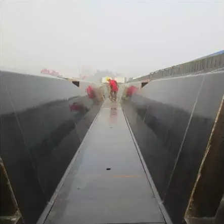
After side formwork installation, both bottom and side formworks are polished and evenly coated with special release paint to reduce contamination during lifting and ensure beam surface quality.
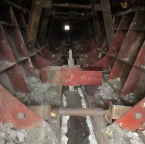
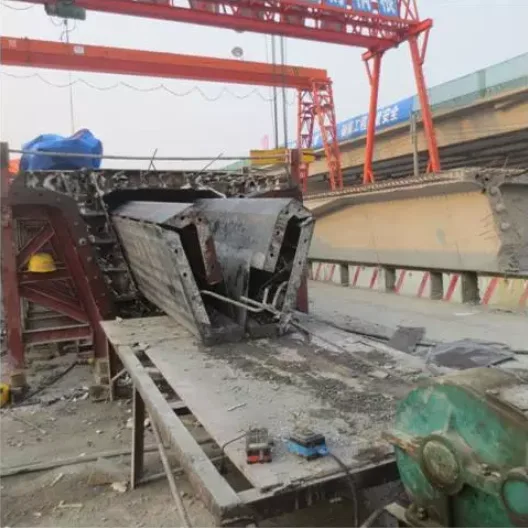
1.3.4 The internal box girder formwork is assembled and adjusted as a unit on a template repair frame, then lifted into place using a gantry crane. This approach reduces past issues with steel reinforcement damage and misalignment during segment assembly and ensures precise beam dimensions and inner box linearity.
1.3.5 Tie rods are designed at drainage holes (reserved 100 mm diameter PVC pipes) on the box girder’s bottom plate to connect the internal formwork’s longitudinal main beam to the bottom formwork, effectively controlling upward movement.
Before concrete pouring, nylon hoses are inserted into corrugated pipes to maintain prestressed duct integrity.
1.3.7 The inner template features a wedge-shaped opening at the flange plate chamfer, combined with a spiral rod for easy disassembly. The inner mold is withdrawn as a whole using a gantry crane and winch, while the outer mold is removed in sections by the crane, reducing labor effort and easing the workload.
Notes:
- After beam reinforcement passes inspection, formwork installation begins with the end formwork, followed by staggered side formwork installation from low to high. Side formworks are lifted sequentially from one end to the other. After installing each side formwork section, lower railing fasteners are connected. Once web reinforcement is completed, inner formwork is installed.
- Adjacent formworks must have tight seams, smooth surfaces with no misalignment, and secure connections.
- After installing all formworks, check the total length and adjust the inner and outer bridge deck widths based on the end formwork centerline. Then tighten all bolts and pull rods sequentially, leveling the side formwork within allowable tolerances.
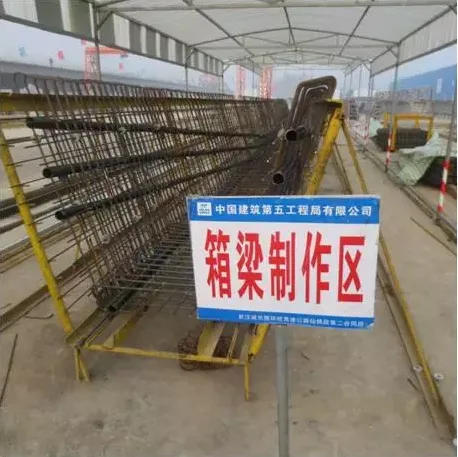
1.4 Construction of Prefabricated Small Box Beam Reinforcement Tire Frame
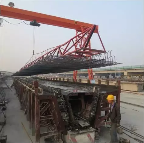
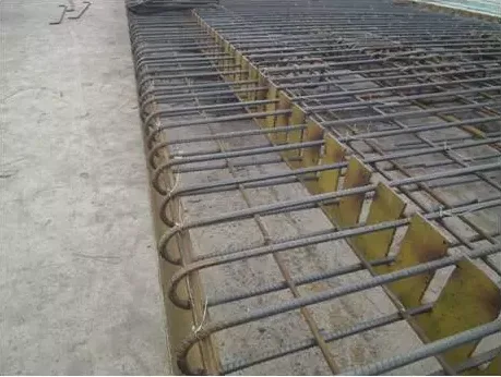
Reinforcement binding is organized according to the beam yard layout, with designated binding areas positioned using tire molds. The bottom web and top plate reinforcement skeletons are bound as a whole and lifted into the mold using a single gantry crane.
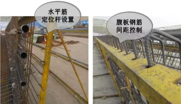
1.4.1 Reinforcement Tire Mold: Constructed from 50 angle steel and steel pipe, the bottom plate reinforcement is precisely grooved on angle steel at positions matching design drawings and longitudinal/transverse bar placement. The groove width is 5 mm larger than the designed reinforcement diameter, with a depth of half the diameter. Web reinforcement is arranged by welding steel bar heads onto steel pipes to position longitudinal horizontal bars accurately, ensuring controllable spacing errors and significantly reducing on-site binding time.
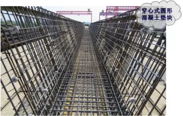
1.4.2 Reinforcement Protection Layer: Uses through-type circular concrete cushion blocks matching the beam’s concrete grade. The inner diameter of these blocks is 3 mm larger than the reinforcement diameter, allowing them to slide freely along the longitudinal bars to prevent displacement, skewing, damage, or detachment during formwork compression, thus ensuring concrete cover thickness control.
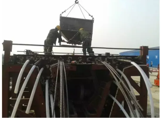
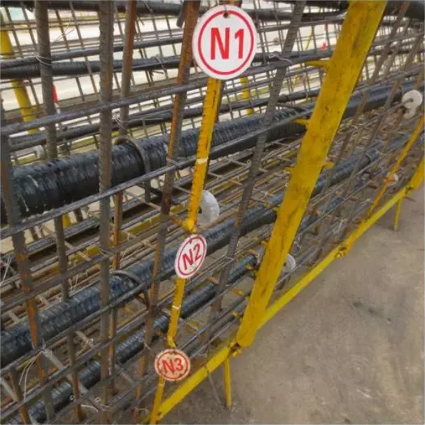
1.4.3 Prestressed Duct Positioning: Adopts a “positioning net” method where corrugated pipes are fixed using “#” shaped positioning bars according to design coordinates. Bars are spaced every 50 cm in curved sections and every 80 cm in straight sections. At pipe joints, a sleeve corrugated pipe approximately 25 cm long with a diameter one size larger is used, secured tightly with plastic tape to prevent loosening, detachment, or grout leakage.
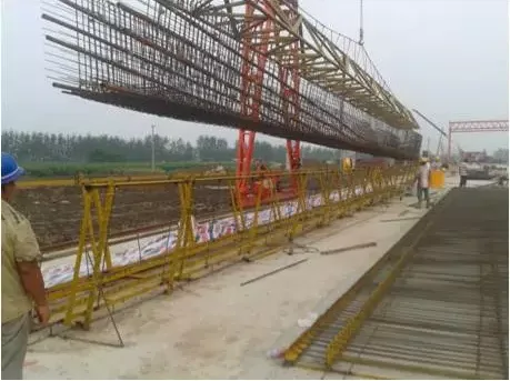
1.4.4 Steel Bar Installation: Steel hangers lift and install the bottom web plate and top plate steel bars as a unit via steel strands. Hangers are welded from steel sections with longitudinal steel strands threaded inside the reinforcement skeleton. Hooks are spaced every 1.5 meters, totaling 17–20 hooks, effectively preventing deformation during lifting and maintaining skeleton integrity.
1.4.5 Transverse Steel Bar Positioning: Comb plates position transverse connection steel bars on the bridge deck. The outer mold features reserved standard holes to accurately position end and transverse connection steel bars, ensuring precise embedded steel bar placement.
Notes:
- Hoop reinforcements are installed vertically. Intersection points between hoop and horizontal reinforcements must be fully tied with binding wire.
- Steel bar installation and binding must ensure firm positioning using galvanized iron wire, tied in a figure-eight pattern with alternating winding directions. For 25 mm diameter bars, double diagonal cross binding is required without deformation or looseness.
- Concrete cushion blocks must have strength ≥ 50 MPa, matching design concrete strength, and be staggered without crossing the entire protection layer. At least four cushion blocks per square meter are required on side and bottom surfaces.
- For metal bellows installation, coordinate positions must be strictly controlled, maintaining good linearity. Corrugated pipe joints use sleeves one size larger than the diameter, wrapped with waterproof tape to prevent loosening or grout leakage.
1.5 Concrete Construction for Prefabricated Small Box Girders
1.5.1 Concrete Pouring Method
Concrete is poured and vibrated diagonally in layers from one end of the beam to the other. The sequence begins with the bottom plate, followed by the web plate. The web plate is poured longitudinally in sections and horizontally in layers toward the opposite end. At 4–5 meters from the beam end, material is distributed from the other end to prevent water and mud accumulation, avoiding uneven beam strength.
To prevent longitudinal cracking at the web-wing plate junction caused by web plate concrete settling, the web plate can be poured first and allowed to settle briefly before pouring the wing plate.
1.5.2 Concrete Vibration
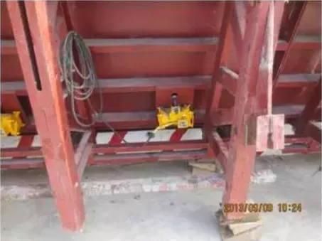
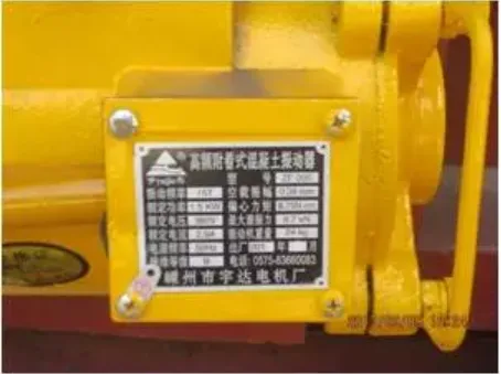
High-frequency attached vibrators are primarily used, supplemented by inserted vibrators, working in combination. Steel plates welded to the back ribs of side formwork include bolt holes sized for the attached vibrators. Ten movable vibrators are arranged per side, spaced every 3 meters, positioned 70 cm from the web plate.
Vibration is intermittent: 20–30 seconds on, 5 seconds off, repeated 6–7 times per concrete layer. The number of active vibrators depends on poured concrete length. Formwork is never vibrated empty. For upper wing plate pours, immersion vibrators are used primarily, with surface leveling during vibration. Use of attached vibrators on wing plates is prohibited.
Due to dense steel bars near formwork and anchor plates, cutting and vibrating simultaneously is necessary. Besides using 30 mm inserted vibrators, 20 mm vibrators address small gap areas during cutting.
1.5.3 Surface Roughening and Chiseling of Prefabricated Small Box Girder Concrete
- Before concrete pouring completion and slurry collection, plaster and level the surface using a leveling ruler to check flatness and cross slope.
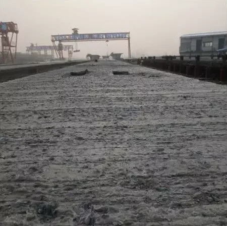
- During initial concrete setting, roughen the bridge deck with steel brushes.
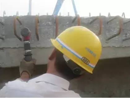
- After demolding, chisel and roughen wet joints and transverse connection joints within 3 cm of concrete edges, using bullet lines for straight edge control.
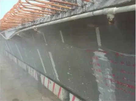
1.5.4 Concrete Curing for Prefabricated Small Box Girders
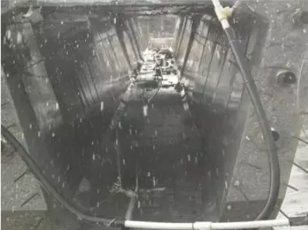
During summer, spray curing is applied using reserved wet joint steel bars to suspend spray pipes that cover the top plate, underside of flange plates, and web plate. Openings reserved for sprinkler pipes inside the box are tensioned with negative bending moments and sprayed with water for curing.
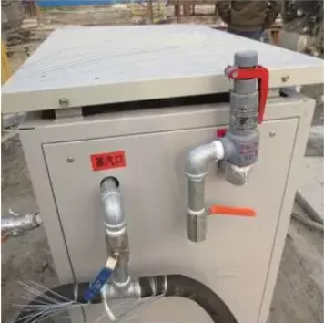
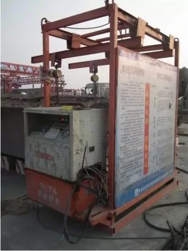
Steam curing is performed inside specially designed curing sheds made from welded 28 mm diameter steel bars and covered with waterproof tarpaulin. The sheds are immediately covered after concrete pouring. Steam is generated by boilers or steam generators and delivered via connected pipes.

Concrete Construction Precautions:
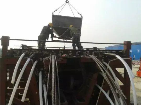
- The BIM engineer directs concrete transport tanker trucks to the beam pouring location. Concrete is evenly poured into molds using gantry crane hoppers. The oblique layering method divides the concrete into 2–4 layers based on beam web plate height. Vibration combines attached and inserted vibrators (50 mm and 30 mm rods).
- Pour belly plates simultaneously on both sides. Monitor bottom plate concrete for leakage at the beam’s bottom corners to determine progress.
- After vibrating the top plate concrete, it is promptly smoothed with a trowel and measured for flatness and cross slope. Between initial and final setting, steel brushes remove surface slurry, followed by cleaning with water.
1.6 Prestressing Tensioning and Grouting of Prefabricated Small Box Girders
Prestressing construction involves anchor preparation and installation, corrugated pipe installation, steel strand cutting and installation, prestressing tensioning, and anchor seal grouting.
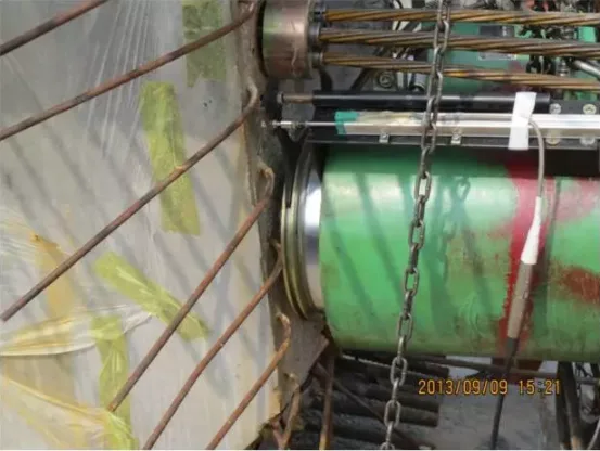
1.6.1 Tensioning Process
Intelligent CNC tensioning equipment synchronizes two jacks via one control box, effectively controlling tension stress and elongation verification.
The oil gauge reading serves as the primary reference during tensioning, with steel strand elongation as verification. The “three control method” holds the load for 5 minutes under controlled stress. If oil pressure drops during holding, it is replenished immediately, and wire slippage is checked. If elongation deviates beyond allowable limits, the technical department identifies causes and provides solutions before proceeding.
Grouting uses vacuum-assisted methods, with mixer speeds over 1000 rpm to ensure slurry quality. Vacuum pumping stabilizes vacuum levels between -0.06 MPa and -0.10 MPa before opening the grouting valve and starting continuous pumping.
Specialized grout ensures precise measurement and quality control during construction. Grouting pressure ranges from 0.5 to 0.7 MPa. Filling continues until grout fully emerges from the duct’s exhaust hole at the opposite end, confirming complete filling.
2. Safety, Civilized Construction Control, and Environmental Protection
2.1 Safety and Civilized Construction Measures
- Establish a safety supervision leadership team to oversee construction safety throughout the prefabricated small box girder process.
- Implement comprehensive safety education and training for all construction personnel, including on-site migrant workers and supervisors, before they begin work.
- Enhance safety awareness through continuous publicity campaigns.
- Place clear and reasonable safety warning signs throughout the construction site to maintain a constant safety focus.
2.2 Safety Precautions for Prefabricated Small Box Beam Construction
- Safety helmets are mandatory for everyone entering the site.
- Temporary electrical systems must be installed and dismantled by qualified electricians.
- Standing behind jacks during girder tensioning is strictly prohibited.
- Specialized equipment must be certified and operated by trained personnel.
- During high-altitude tasks, workers must wear safety belts and non-slip footwear.
- Designated storage areas are required for flammable and explosive materials, managed according to regulations.
2.3 Environmental Protection Measures
- Install sedimentation tanks to treat all construction wastewater before discharge.
- Collect construction waste at designated locations; avoid random disposal.
- Properly store oils like diesel and engine oil to prevent spills and environmental contamination.


Must log in before commenting!
Sign Up