Every bridge engineer inevitably encounters the challenge of working with beams. The two most common methods for beam fabrication are prefabrication and cast-in-place. Among these, the prefabrication process—when executed to standard—holds unparalleled value in bridge engineering.
1. General Provisions
1. Approval and disclosure of the commencement report and other technical documents for the sub-projects must be completed.
2. Construction of the pedestal, tensioning platform, and gantry crane safety inspections must be finalized.
3. All mechanical equipment for prefabricated beams—such as jacks, oil pumps, steel processing machinery, and grouting machines—should be onsite. Tensioning equipment must be calibrated.
4. Tensioning operators must be equipped with walkie-talkies to ensure timely communication and coordination on site.
5. All raw materials must undergo testing and meet regulatory requirements.
6. The construction mix ratio must be approved by supervisors, and steel strands, corrugated pipes, anchorages, etc., should pass outsourced testing.
2. Prefabrication Yard Construction
2.1 Selection and Planning of the Prefabrication Yard
1) Dedicated power and water lines must be established at the prefabrication site. Unauthorized connections are strictly prohibited. These utilities should be planned, constructed, and operational simultaneously with the yard construction.
2) Adequate automatic sprinkler systems must be installed for beam curing, based on the curing duration and number of pedestals. Curing water pipes and steam curing pipelines should be pre-laid to ensure complete coverage, especially under the bottom flange plate and transverse partitions. Proper drainage systems must be in place, along with measures to prevent ground subsidence.
3) The number of pedestals should be planned according to the total number of box girders for the entire bridge, following the empirical formulas below:
A × T ≥ D;
B = 2A;
B × T ≥ 2D (i.e., B ≥ 2D/T),
where A = daily prefabricated beams; B = minimum number of template sets; T = total beam erection duration; D = total required beams.
4) The bottom mold must use full-length steel plates, 6–8 mm thick, with flatness deviations not exceeding 2 mm and height differences at the ends no greater than 5 mm. The plates should be smooth and flat, treated promptly with release agents, and protected against contamination.
5) Anti-arching arrangements must comply with design and linear specifications, ensuring pedestal sides are straight and equipped with measures to prevent grout leakage.
3. Construction Technology
3.1 Post-Tensioning Construction Process:
Clean bottom formwork and set construction layout → assemble side and end formworks → bind bottom and web reinforcement → install prestressed ducts → place internal formwork → bind top reinforcement → pour concrete → cure beams → tension and grout → anchor and seal beam ends with concrete.
4. Key Construction Points
4.1 Steel Bars
1) Cutting, processing, positioning, binding, and welding of steel bars must adhere strictly to specifications and design drawings.
2) Use hemispherical high-strength mortar cushion blocks for the steel bar protective layer wherever possible; these should be firmly and securely tied.
4.2 Formwork
1) Before use or after removing formwork from each beam, assign a dedicated person to carefully polish the formwork and apply a specialized release agent.
2) Use internal molding rods or fix internal molds with ground anchors to prevent uplift.
4.3 Corrugated Pipes and Anchor Plates
1) During steel bar binding, accurately fix the position of corrugated pipes and anchor plates according to design.
2) Connect corrugated pipes using pipes of the same type but with a diameter one size larger. The joint length should be 5–7 times the inner diameter of the connected pipe and must meet specification requirements. Seal connections with sealing tape to prevent grout leakage.
3) Anchors and anchor plates must be approved and tested before use. Reinforcing bars and spiral bars beneath anchors should be arranged per design, with spiral bars matched to anchor plates.
4.4 Concrete
1) Follow the “staircase” pouring method strictly. When pouring the bottom plate, use the reserved concrete funnel on the top plate and proceed with continuous pouring at 5-meter intervals to ensure concrete integrity.
2) Prefabricated beams must include test blocks cured under identical conditions. Place these blocks on the beam’s top plate and cure them alongside the beam.
4.5 Prestressing Construction
1) Steel strands must be bundled.
2) Control concrete curing time and strength before tensioning: The concrete strength must meet or exceed design requirements, and tensioning should only commence once rebound strength reaches the specified level.
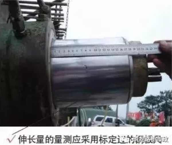
3) Tensioning uses dual control of force and elongation. Hydraulic jack displacement cannot be directly measured. Symmetrical tensioning at both ends is common, following the formula: L = L – L1 + (L1′ – L1), where L1 corresponds to 20% tension (or 15%), δk at 100%, and L1′ at 40% (or 30%) δk.
4) Prestressed steel strands may only be anchored once the tension control stress stabilizes.
4.6 Grouting
1) Vacuum grouting technology should be used for box girder grouting. Each precast beam yard must have a set of vacuum grouting equipment ready to meet construction needs.
2) Construction requirements:
① Use special grouting materials or slurry prepared with a dedicated grouting agent. Control water-cement ratio between 0.26 and 0.28, and initial flow time should not exceed 13 seconds.
② During grouting and when temperatures drop below 5°C within 2 days after grouting, apply steam curing for one day.
③ Cement slurry injection must be continuous. Allow waste slurry to flow out of the outlet until it is free of water foam gas, stopping injection simultaneously with the slurry.
3) Qualified testing agencies should perform grouting quality tests on prestressed pipelines. Testing frequency is 5% of prefabricated beams and 10% of corrugated pipes in cast-in-place beams and continuous rigid frame bridge cantilever beams.
4.7 Chiseling
For wet joints and beam ends where concrete surfaces require chiseling, use specialized or electric chisels immediately after demolding.
4.8 Beam and Slab Curing
1) Prefabricated beams and slabs are generally cured by connecting the pre-embedded steam pipeline to the sprinkler system. Use pressurized water to maintain moisture and cover the top plate with geotextile to retain humidity. Curing duration should be based on rebound strength.
2) For winter curing, after mold removal, immediately cover beams with flame-retardant tarpaulins and apply boiler steam curing.
4.9 Additional Requirements
1) When prefabricating box girders, ensure all design-required embedded parts—such as expansion joint bars, drainage holes, anti-collision guardrail bars, suspension beam holes (rings), and steel bundle holes—are installed accurately.
2) Prior to storage, conduct a thorough visual inspection of beams and slabs, focusing on length, slope of pre-embedded steel plates at the beam bottom, and crack detection. This helps identify defects early and avoids re-lifting after installation.
3) During prestressed steel bar tensioning, no personnel should stand in front of the beams. Set up barriers and warning signs for safety.
4) Stacking height limits: box girders should not exceed two layers, slab girders no more than three. Regularly inspect foundation stability in the storage area.


Must log in before commenting!
Sign Up