Preface
Prestressed concrete hollow slabs offer many advantages, including consistent product quality, long spans, high load capacity, flexible design options, excellent spatial effects, ease of construction, and relatively low overall costs. In recent years, they have been widely adopted across numerous cities in China. Typically, the traditional construction method involves first casting the beams, which then serve as supports for the prestressed concrete hollow slabs.
However, the conventional method has notable drawbacks. The ring beams must be poured and reach a certain strength before prefabricated slabs can be installed, leading to slower construction progress. Additionally, the highly brittle nature of prestressed concrete hollow slabs makes them susceptible to longitudinal cracking during lifting, complicating the achievement of strong connections between prefabricated and cast-in-place elements.
To address these limitations, the applying unit of this method has developed an integrated construction technique combining prefabricated prestressed concrete hollow slabs with cast-in-place beams. This method employs a rigid frame to support the hollow slabs and enhances the overall structural capacity by incorporating two types of embedded components, thereby strengthening the connection between prefabricated and cast-in-place structures. The developers have filed an invention patent for the “Integrated Construction Method of Prefabricated Prestressed Concrete Hollow Slabs and Cast-in-Place Beams” and a utility model for the “Integrated Construction Structure of Prefabricated Prestressed Concrete Hollow Slabs and Cast-in-Place Beams.” This technology has been successfully applied in practical projects, yielding significant economic and social benefits. Our team has compiled the construction technology and experience, refined the enterprise-level method, validated it through engineering practice, improved the process, and finalized this documentation. According to the Zhejiang Provincial Institute of Science and Technology Information, several core technical aspects of this method fill existing gaps in China’s construction technology.
Characteristics of the Construction Method
2.1 This approach uses a rigid frame formwork support system, enabling simultaneous lifting of hollow slabs and beam construction, which significantly improves construction efficiency.
The adjustable top screw bolts of the prestressed concrete hollow slab support system prevent common issues like uneven slab bottoms, ensuring better conditions for subsequent construction steps.
2.2 Pre-embedded steel plates are welded at the top of the beams to act as auxiliary supports for the hollow slabs, guaranteeing high-quality lifting.
2.4 Embedded screws inside the beams, combined with fixed steel plates on top, effectively integrate the prefabricated and cast-in-place structures, enhancing load-bearing capacity and structural integrity.
2.5 This method eliminates the need for applying cement mortar leveling layers on ring beams and filling joints with fine aggregate concrete at slab ends, enabling integrated construction that reduces costs and delivers strong economic benefits.
2.6 Because the rigid frame formwork supports the hollow slabs, the strength requirements for concrete dismantling and lifting do not directly impact subsequent construction steps, shortening the time needed per structural layer and accelerating project progress.
Scope of Application
This method is suitable for the simultaneous installation of cast-in-place beams and prestressed concrete hollow slabs in floor construction projects.
Process Principle
The method involves constructing prestressed hollow floor slabs using a rigid frame formwork and embedded components to achieve integrated construction of hollow slabs and cast-in-place beams. The resulting structure is solid, reliable, and easy to build.
The integrated structure mainly consists of a prestressed hollow slab support system, beam formwork reinforcement system, and fixed steel plates. The support system is erected using scaffolding, equipped at the top with adjustable screw bolts, top supports, timber beams, and plastic gaskets. Embedded steel plates are welded to the tops of the beam reinforcements, with bolts welded at their bases. The beam formwork reinforcement system includes side and bottom formwork, main keel double steel pipes, and secondary keel wooden beams. Fixed steel plates are installed at the slab-beam junctions and secured to the cast-in-place beams via screws and bolts.
The top of the hollow slab support system features adjustable screw bolts welded to top supports, with wooden blocks and plastic gaskets placed at contact points with the hollow slabs. Pre-embedded steel plates are welded on both sides of the beam reinforcement tops as part of the support system. Embedded screws within the beams are tied to the main steel bars, and concrete is poured and sealed. Fixed steel plates located at slab-beam junctions are fastened with nuts and embedded screws, covered by a concrete surface layer that integrates with the prefabricated slab. During pouring, steel wire mesh is laid at the hollow slab joints, embedded within the concrete surface layer.
Process Flow and Key Operations
5.1 Construction Process Flow
The integrated construction process for prefabricated prestressed concrete hollow slabs and cast-in-place beams is illustrated in Figure 5.1.
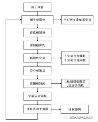
Figure 5.1 Integrated Construction Process Flow Chart of Prefabricated Prestressed Concrete Hollow Slabs and Cast-in-Place Beams
5.2 Key Operation Points
5.2.1 Construction Preparation
Prepare all necessary tools and materials according to prestressed concrete installation requirements. Familiarize with the process before starting, allocate machinery and labor efficiently, and ensure material availability. Inspect prefabricated hollow slabs for quality, confirming factory certificates of conformity. Check for visible defects such as cracks, missing corners, or warping; replace defective components immediately. Store slabs on a flat, stable area with adequate drainage. When stacking, ensure correct orientation to avoid damage. Stacks should not exceed 10 slabs, with wooden pads between layers.
5.2.2 Scaffolding Installation
1. Perform positioning and layout as specified; place 4m-long, 50mm-thick cushion plates accurately along positioning lines. Ensure connecting fasteners on adjacent poles are staggered, with no more than 500mm between joints and main nodes.
2. Position longitudinal horizontal poles inside the uprights, spanning at least 3 sections. Connect longitudinal and horizontal bars using staggered docking fasteners, avoiding synchronized joints within the same span.
3. Install horizontal bars at main nodes, secured with right-angle fasteners, which must not be removed. Set non-node horizontal bars at equal intervals (max spacing 750mm) to support scaffold boards, fixing ends to longitudinal bars with right-angle fasteners.
4. Hang a green dense mesh safety net inside the outer poles, with a horizontal safety net every four layers.
5. Install adjustable top screw bolts at scaffold-top-to-hollow slab contact points, welded to top supports with wooden blocks and plastic gaskets beneath.
5.2.3 Beam Bottom Formwork Installation
1. Lay 100mm × 100mm square timber on adjustable top supports, aligning longitudinal joints with supports and staggering joints to avoid alignment. Secure timbers with nails. Then, lay 10mm × 100mm square timber perpendicularly at 300mm spacing, staggering joints and ensuring all timbers are straight.
2. After two timber layers are in place, mark the bottom plate centerline. Lay 18mm thick bamboo plywood (2.44m × 1.22m) on both sides, fastening tightly to square timber with iron nails. Align edges carefully and seal joints with double-sided tape to prevent grout leakage.
5.2.4 Beam Reinforcement Binding
1. Thread lower longitudinal and bent steel bars of the main beam, place stirrups on main and secondary beams, and tie them firmly at specified intervals.
2. Ensure upper longitudinal steel bars pass through the mid-node, and lower bars extend with sufficient anchorage length meeting design specifications.
3. Tie hoop reinforcement on upper beam longitudinal bars using buckle methods; stagger bent hooks at overlaps. Hooks should be bent at 135°, with straight parts of 10 times the bar diameter (10d). For closed hoops, weld seam length should be 5d on one side.
4. For load-bearing bars ≥22mm diameter, use welded joints; for bars <22mm, tied joints are acceptable, with overlap lengths per specifications. Joints must be at least 10 times the bar diameter away from bending points and not located at maximum bending moment zones. Tie lap joints firmly and stagger joint positions, limiting joint cross-sectional area to 50% in tensile zones.
5.2.5 Installation of Embedded Components
Before welding embedded parts, verify steel bars, plates, screws, and other components meet design and mandatory standards. Resolve any discrepancies before proceeding. Weld pre-embedded parts using arc welding; inspect for defects such as undercuts, porosity, slag inclusion, insufficient penetration, or indentations. Remove defects promptly. When hand welding, ensure fillet weld height meets standards and control current to avoid steel bar burn-through.
1. Pre-embedded screws: Tie pre-embedded screws to positioning steel bars, connect to main beam reinforcement, then weld and fix screws (M50, 40cm length) at specified intervals.
2. Pre-embedded steel plates: Weld 16mm-thick steel plates on both sides of beam reinforcement tops in segments, with bolts welded at plate bases.
5.2.6 Hollow Slab Hoisting
1. Suspend the prestressed concrete hollow slabs only after completing beam reinforcement, formwork, and support system adjustments and inspections. Mark position and slab seam lines on wooden blocks atop the formwork. To accommodate structural columns or frame columns on the floor, cut slab corners as needed, keeping corner widths within one-fourth of the slab width; reinforce if exceeded. Slab ends can also be cut to curves if required. Inspect slab openings for blockages or surface defects; only approved slabs may be used.
2. For slab lifting: Conduct trial lifts to verify support stability before formal lifting. Identify panel openings (for heating, plumbing, electrical conduits) and directional markings. Confirm panel models match room design requirements, accounting for a 5cm slab thickness plus 50mm joint with cast-in-place slab. Lift panels individually per layout plan, align slab ends with supports, and lower slowly. After stabilizing and confirming support lengths meet requirements, release lifting hooks. Continuously monitor support stability to prevent accidents.
3. Adjust slab positioning: After lifting and unhooking, adjust support lengths at slab ends as needed to meet design specifications.
5.2.7 Beam Side Formwork Assembly
After installing and aligning the beam bottom formwork, assemble side formworks on both sides. Control the height of the upper formwork openings carefully. Install wooden keels at 400mm intervals and double steel pipe main keels also at 400mm intervals. Connect side formwork securely to the bottom formwork and apply rubber strips to seal joints. Fix formworks with nails and reinforce with steel pipes and wooden beams. Verify centerline, elevation, and beam cross-sectional dimensions.
5.2.8 Installation of Slab Joint Formwork
The prestressed concrete hollow slab joint measures 50mm at the upper opening. Use iron wire-hung foot tubes or square wood for the joint formwork. If square wood is used, reduce corner size by 15mm. Seal contact surfaces between steel pipes or wood and hollow slabs with sealing strips, recessing pipes or wood 10mm into the joint.
5.2.9 Cast-in-Place Beam Pouring
Use commercial concrete and pour beam and slab joint concrete in one continuous operation. To control cracking and maintain flatness at board joints, observe the following:
1. Use fine aggregate concrete with strength ≥ C20 or cement mortar with strength ≥ 20 N/mm².
2. Ensure fine aggregate concrete has good workability to fill key slots tightly.
3. Before grouting, stabilize adjacent boards with temporary supports or fixtures to maintain flatness.
4. Use concrete with the lowest possible water-cement ratio for joints.
5. Add a micro-expansion agent to the poured concrete as appropriate.
6. Key grouting points:
- a. Evenly distribute fabric; construction load should not exceed 2.5 N/m².
- b. Ensure reliable formwork support or suspension.
- c. Clean joints thoroughly before grouting.
- d. Fully moisten board joints.
- e. Carefully vibrate or compact joints with thick steel plates.
- f. Perform watering, covering, and curing.
- g. Remove formwork within the specified time.
- h. Prevent damage from construction loads.
If fine aggregate concrete strength is less than 10 N/mm², avoid walking on the slab surface.
5.2.10 Installation and Fixing of Steel Plates
After concrete pouring, install fixed steel plates during the initial concrete setting phase to improve bonding. Align reserved screw holes with embedded screws, then partially flatten the steel plate and tighten nuts securely.
5.2.11 Pouring Concrete Surface Layer
1. Template installation: Use steel templates that are undamaged and sufficiently strong. Ensure interior, top, and bottom surfaces are smooth and straight, with local deformation under 3mm. During vibration, lateral deflection should be under 4mm, and height must match the concrete slab thickness with ±2mm tolerance. Tie rod hole positions on longitudinal joint templates must be precise; tongue-and-groove length errors should be ±1mm for steel and ±2mm for wood.
2. Concrete pouring: Use C20 concrete or cement mortar for the surface layer. Smooth the surface manually or mechanically before final setting. Lay steel wire mesh at prestressed hollow slab joints, embedded within the surface layer.
Materials and Equipment
6.1 Main Materials
Materials must meet design requirements for prestressed concrete hollow slabs. Use ordinary Portland cement with strength ≥ 32.5 grade, complying with GB175-2007 standards. Yellow sand should be clean medium sand meeting JGJ52-2006 standards. Stones must be crushed, sized 5-12mm, and comply with JGJ5392 standards. Other materials include 16mm thick steel plates, 40cm long M50 screws, wooden boards, 100mm × 100mm wooden squares, 18mm thick plywood, steel pipe scaffolding, buckles, steel wire mesh, top screw bolts, and wooden wedges.
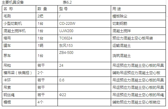
6.2 Main Equipment
The primary machinery and equipment are detailed in Table 6.2.
Engineering Quality Control Standards
This method adheres to the following main standards and regulations:
- 1. Unified Standard for Construction Quality Acceptance of Building Engineering GB50300-2013
- 2. Code for Acceptance of Construction Quality of Building Foundation Engineering GB50202-2002
- 3. Code for Acceptance of Construction Quality of Reinforced Concrete Structures GB50204-2015
- 4. Design Specification for Mix Proportion of Ordinary Concrete JGJ55-2011
- 5. Design Specification for Mix Proportion of Masonry Mortar JGJ98-2011
- 6. Quality Standards and Inspection Methods for Sand Used in Ordinary Concrete JGJ52-2002
- 7. Technical Specification for Application of Concrete Admixtures GBJ119-2013
- 8. Prestressed Concrete Hollow Slabs Standard GB/T 14040-2007
7.2 Quality Assurance Measures
Before scaffolding installation, verify positioning axes, foundation axes, and the placement and elevation of building anchor bolts. Inspect and accept the foundation, ensuring concrete strength meets design requirements. Benchmark points for axes and elevations must be accurate and complete.
7.2.2 Carefully plan raw material lengths and mixes, controlling steel bar joint counts per section to meet specifications.
7.2.3 Ensure steel bar joint locations, stirrup spacing, and bending angles comply with construction specs and design; conduct concealed acceptance inspections.
7.2.4 Schedule water and electrical pipeline pre-embedding during steel reinforcement processes to avoid damage or removal of tied reinforcement.
Before formwork support installation, mark formwork positions on the bottom surface accurately.
7.2.6 Install templates with tight, smooth joints, preventing grout leakage, displacement, mold shifting, expansion, or deformation.
7.2.7 Control concrete pouring speed to about 0.5m height per pour and approximately 15 minutes between pours, reducing lateral pressure on formwork and preventing damage.
While concrete work is straightforward and reduces labor intensity, strict construction management and process control are essential.
7.2.9 Inspect quality of each prefabricated hollow slab batch upon delivery, ensuring compliance with specifications. Stack slabs on flat, solid ground with full-length pads under the first slab and short pads between layers, aligned vertically and firmly secured, limiting stacks to 10 layers and 2.0m height. Position wooden pads 200-300mm from slab ends, aligned and compacted, avoiding missing corners. During stacking, lifting, and transport, do not flip or place slabs on their sides. Transport slabs according to stacking requirements without drilling holes.
7.2.10 Connect the prestressed hollow slab support system and formwork support system into a rigid, strong, and stable unit to prevent slab deformation or displacement after installation. Place cushion plates under all vertical supports. For large-span slabs supported on reinforced concrete eaves, verify bearing capacity and shear conditions; if inadequate, increase eave thickness and reinforcement accordingly.
Before slab installation, ensure factory certificates and concrete strength meet design and construction standards. Inspect slab appearance, rejecting those with cracks or surface damage.
Before pouring composite concrete layers, clean and thoroughly moisten slab tops without water accumulation. Compact concrete carefully using flat vibrators to ensure integration with prestressed slabs. Cover and cure after initial setting.
7.2.13 Apply pressure to the concrete surface 2-3 times before final setting to prevent micro-cracking.
7.2.14 Adjust slab positioning during lifting to maintain consistent support lengths at both ends, avoiding insufficient support at either end.
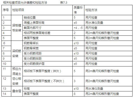
7.3 Quality Inspection
Main inspection criteria at each construction stage are summarized in Table 7.3.
Safety Measures
Safety protocols comply with the following standards: “Construction Safety Inspection Standard” (JGJ59-2011), “Technical Code for Safety of Temporary Electrical Use on Construction Sites” (JGJ46-2012), “Standard for Equipping and Using Labor Protection Equipment for Construction Operations” (JGJ184-2009), and “Technical Regulations for Safety of Construction Machinery Use” (JGJ33-2012). Key measures include:
During high-altitude welding, store replacement electrode heads centrally to avoid injury from falling materials.
8.2 Handheld electric tools (e.g., electric chisels, drills) must meet electrical safety standards. Power cords, plugs, and sockets should be intact and properly maintained. Avoid unauthorized extension or modification. Assign dedicated personnel for tool maintenance and storage.
8.3 Store non-reusable templates on designated racks after removal to prevent slipping or tipping.
When pouring beam concrete, erect operating platforms with waist- and sweeping-level railings, lay scaffold boards, and prohibit workers from standing on beam bottom formwork or formwork openings.
During concrete vibration, withdraw rubber hoses slowly to prevent falls or injuries due to their length.
Assign dedicated staff to oversee scaffold bottom support during concrete pouring to prevent accidents.
Environmental Protection Measures
Environmental measures follow “Environmental and Health Standards for Construction Sites” (JGJ146-2013) and “Emission Standards for Environmental Noise at the Boundary of Construction Sites” (GB12523-2011). Key practices include:
9.1 Comply with national environmental laws, manage construction sites to prevent pollution or environmental damage, reduce machinery noise, and prohibit noisy machinery operation from 10 PM to 6 AM unless approved by local authorities with public notification.
9.2 Minimize construction noise using technical and management controls, avoiding night operations near residential areas where possible. Employ low-noise equipment for tasks like bridge drilling.
9.3 Implement dust control measures to keep pollution within permitted levels and clean ground dust promptly.
9.4 Properly dispose of construction and daily waste in approved locations, avoiding river contamination. Seal transport vehicle cargo compartments and use specialized tanks for drilling mud transport. Prevent loss if immediate disposal is not possible.
9.5 Organize and manage construction materials in designated temporary storage areas to prevent loss or damage.
9.6 Require all work teams to clean sites after completion, removing excess materials and debris. Assign dedicated personnel for site inspection and cleaning, ensuring neat material stacking and overall site tidiness.
Benefit Analysis
10.1 Technical Benefits
By using rigid frame formwork to install prestressed concrete hollow slabs, construction does not have to wait for concrete to reach design strength before proceeding to the next layer. Simultaneous lifting of hollow slabs and cast-in-place beams accelerates material turnover, shortens construction periods, and speeds project completion. This method reduces formwork support, steel bar processing and installation, and concrete pouring and curing efforts, significantly improving efficiency and reducing costs. Overall, it addresses common challenges in prestressed hollow slab construction and enhances quality with clear technical advantages.
10.2 Economic Benefits
Using precast hollow slabs reduces construction costs compared to cast-in-place floors, saving approximately 1,200 yuan per 100 square meters in materials. Integrated pouring reduces labor by 20%, saving about 1,800 yuan per 100 square meters. Construction efficiency increases by roughly 25%, saving 2 hours per 100 square meters, which equates to 2,000 yuan in labor savings and 20% in machinery rental fees. Overall, this method cuts floor slab construction costs by approximately 9–15%.
10.3 Social Benefits
The integrated construction method promotes material turnover throughout construction, resulting in low energy consumption. It facilitates convenient disposal of waste, sewage, and other materials, effectively protecting the surrounding environment and minimizing pollution. Production waste is centrally managed; recyclable materials are promptly collected, and non-recyclables are properly disposed of. Consequently, this method delivers substantial social benefits.


Must log in before commenting!
Sign Up