Tianzheng Water Supply and Drainage Software supports Windows 7 (32/64 bit) and Windows 10 (64 bit) operating systems. It is compatible with CAD platforms including 32-bit AutoCAD 2010–2016 and 64-bit AutoCAD 2010–2022. The software features a convenient and comprehensive indoor module that allows quick floor plan layouts, system diagram generation, and calculations for various systems.
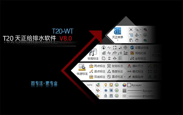
The latest version introduces a redesigned interface with a new layer manager. It retains the Tianzheng layer standards pre-set into the manager, organizing layers into groups for clearer management and easier operation. The ‘Transparent Bar’ option enables locked layers in the image to display transparently, adjusting their brightness according to transparency settings.
The flat menu is divided into indoor and outdoor sections, allowing users to customize the menu bar styles. Multiple methods are available for accessing functions, including screen menus, shortcut menus, toolbars, and customizable shortcut keys, maximizing user convenience and adaptability.
Tianzheng Water Supply and Drainage T20V8.0 Installation and Activation Guide
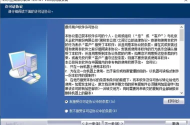
- Download and run the T20 Tianzheng Water Supply and Drainage Software T20-TWT V8.0 installer. Accept the license agreement. (Note: The official version has been updated.)
- Select the installation path, typically the default
C:TangentTWTT20V8sys24x643. Follow the installation steps until completion, then exit the installer. - Copy the patch file
tch_initstart.arxinto the installation directory, replacing the original file. (Default path:C:TangentTWTT20V8sys24x64) - Launch the software and associate it with CAD.
New Features in Tianzheng Water Supply and Drainage T20V8.0
- Supports 64-bit CAD2022 platform.
- Single-tube pipeline entities now support variable diameter display with added style options.
- Supports valve insertion and display on single pipe riser objects.
- Added “Enter Elevation” command shortcut for pipeline drawing.
- Optimized positioning box for vertical pipe entities.
- Improved positioning box selection and display functions in riser layout.
- Enhanced multi-tube drawing dialog box.
- Added “Pipeline Interruption” feature to select and add broken pipe symbols.
- Optimized pipeline connection and break symbol deletion when adding pipe break symbols at pipeline ends.
- Inserted valve objects on single pipe riser objects.
- Improved dialog box size memory function for valve components.
- Added nozzle statistics function.
- Water tank custom entity now includes manhole pickup points for easier relocation.
- Added custom entities and arrangement functions for water collection pits.
- Optimized well layout with commonly used pipeline system buttons, upgraded layer standards, and separate indoor/outdoor pipe materials.
- Real-time adjustment of elevation, slope, and diameter of well pipes during layout.
- “Number Annotation” dialog now supports adjusting distance between text and lines.
- “Number Adjustment” command line prompts for adjusting object numbers.
- “Chief Manager Annotation” supports dialog box selection of operation methods.
- Supports elevation rise and fall annotations with multiple lines of text.
- Added outdoor pipe settings to the layer standard tgsl file.
- New Tianzheng layer added to the tgsl layer standard file.
- Image label page numbering supports sorting and adjustment.
- Added support for contour line extraction in elevation collection.
Bug Fixes
- Resolved issue where pipe diameter annotation was disabled if slope or pipe length annotation existed.
- Fixed inconsistent layer creation when drawing at scales other than 1:100.
- Prevented unnecessary pipe break symbols when connecting equipment like pipelines.
- Fixed multi-tube drawing dialog close button not exiting properly.
- Corrected equivalent values for pipe fittings in spray calculation dialog.
- Prevented repeated floor line markings when vertical pipes were broken in system diagrams.
- Fixed missing vertical pipe annotations in system generation.
Generating Longitudinal Section Diagrams in Tianzheng T20V8.0
This process organizes pipeline plans and extracts longitudinal section data such as pile numbers, elevations, and well numbers. The data can then be edited and exported to Excel. Elevation data extraction uses the software’s vertical elevation extraction feature based on pile numbers. It is important to arrange pile distances consistently to minimize processing complexity.
Inspection well data compilation involves entering pile numbers extracted from floor plans into the well pile number column. This matches measurement point mileage and slope change mileage data, allowing for seamless integration and calculation of distances between wells using Excel formulas.
Feature well data can be updated by pasting spacing and station number data from inspection well data and editing elevation data to correspond with respective station numbers.
Interior Design
Intelligent Pipeline System
The pipeline settings offer powerful customization, allowing users to define pipeline names, line widths, linearity, pipe materials, and other parameters to meet design requirements. Custom information applies to pipeline drawing, riser drawing, and system generation.
The software employs 3D pipeline design, automatically generating pipeline nodes and enabling precise connections between pipelines, equipment, and valves through fuzzy operations. Occlusion processing is handled automatically to maintain the integrity of individual pipelines. Position changes to intersecting pipelines, equipment, or text trigger automatic occlusion updates. Pipeline annotation remains consistent with graphics, ensuring accurate calculations and statistics.
Quick Connect Sanitary Ware
This function enables filtering of sanitary ware types and parameter assignment based on the latest “Sanitary Ware Installation Atlas” (09S304). With one-click box selection, users can connect pipelines to sanitary ware, automatically parameterize sanitary ware graphics, and identify types. It accommodates differences in exposed versus concealed water supply installations and inspects for cross-collisions between multiple pipelines. The result is compliant, clean, and visually appealing drawings.
Pipeline Linkage
Selecting a pipeline allows for the simultaneous movement of associated valves, bends, and accessories, as well as automatic extension of connected pipes.
System Diagram Generation
The software automatically generates system diagrams and provides editing tools for refinement. It reads system diagram data for hydraulic calculations in public building water supply, generates calculation sheets, and annotates pipe diameters. Users can customize text size, style, line widths, colors, line types, and riser circle sizes to suit individual preferences.
Sprinkler and Fire Protection
The software supports fire hydrant system design, including selection of single or double hydrants and connection methods. Fire pipelines automatically locate fire hydrant connection points. After pipe diameter annotation, hydraulic calculations and output of calculation sheets are supported. Protection radius functions ensure compliance, marking overlapping water spray areas with diagonal lines for easy verification.
A new ‘Fire Extinguisher Layout’ command allows placement of individual extinguishers or selection of fire hydrants for extinguisher placement. Fire extinguisher displays reflect actual quantities and can be annotated.
Fire calculation features include dialog box controls, location determination for pressure-reducing and stabilizing hydrants, and compliance with GB50974-2014 technical specifications.
Spray equipment arrangement options include arbitrary, straight nozzle, rectangular nozzle, equidistant nozzle, fan-shaped nozzle, and curved nozzle layouts, which can be combined as needed.
Sprinkler calculations determine system inlet pressure based on building hazard levels or inlet pressure to calculate the most unfavorable nozzle pressure, completing the calculation sheet in Word. Post-calculation, flow velocity for each pipe section is automatically determined for real-time diameter adjustments and recalculations.
Water Pump and Water Tank Room
The software supports selection of water pumps and drawing of water pump and tank room plans. Section views can be automatically generated. Double-line water pipes are supported, with valves directly insertable into risers, an advantage over competing software. The water pump room is also viewable in 3D.
Water pump selection is optimized with updated database information, including plans, elevations, sections, installation, and 3D drawings.
Professional Computing
The software reads system diagrams for water supply and drainage hydraulic calculations, generates calculation sheets, and annotates pipe diameters. Personalization options include text size, style, pipeline line width, color, line type, and riser circle size.
Calculation functions cover:
- Hydraulic calculations for building water supply systems using outflow probability (residential) and equivalent methods (public buildings).
- Drainage system hydraulic calculations using the equivalent method.
- Automatic sprinkler fire extinguishing system calculations using the action area method.
- Fire hydrant system hydraulic calculations via schematic diagrams.
- Daily water consumption calculations, including maximum daily, peak day/hour, and average consumption.
- Water tank volume calculations for appropriate tank selection.
- Calculations for pneumatic water pipe working pressure and volume.
- Water storage tank volume calculations.
- Pressure relief orifice plate calculations (pressure and aperture).
- Fire extinguisher level requirement calculations.
- Hydrant outlet pressure and protection radius calculations.
- New residential simplified calculations for rapid flow diameter and velocity assessment.
- Gas fire extinguishing calculations for heptafluoropropane IG541, including design dosage and pressure relief port area for hot aerosol.
Siphon Rainwater Module
This module is ideal for large buildings such as sports stadiums and industrial plants. It quickly calculates roof rainwater flow rates using catchment division, area, and roof calculations. Based on this, rainwater hoppers are arranged and suspension and discharge pipes drawn.
After arranging the flat siphon rainwater system, calculations for pressure margin, maximum negative pressure, and other parameters can be performed and verified.
Outdoor Design
Outdoor well layout is simple and fast, offering arbitrary layout, fixed distance along a line, fixed distance single layout, and two-point fixed distance options. Inspection wells (circular, square), valve wells, drop wells, and water seal wells can be quickly placed with automatic well number annotation.
Pipeline slope direction can be defined based on well layout, and connections between wells and entrance/exit pipelines are automatic. Pipeline drawing inherits indoor module advantages and adds frozen soil depth detection for real-time burial depth checking.
Various pool body options are available with easy insertion. The system automatically tracks pipeline direction and disconnections. Sludge volume is calculated automatically, and a national standard septic tank atlas is provided for reference.
Functions such as rainwater outlet, fire hydrant, and stake drawing enable rapid outdoor infrastructure design. Rainwater outlets can be drawn along roadsides and linked automatically to rainwater wells. Fire hydrants can be laid out outdoors efficiently.
Batch annotation of pile numbers or other markers is supported based on reference road lines, with annotation positions selectable as left, right, or center according to road direction.
The software supports drawing roads, pipelines, and structures, facilitating well arrangement and annotation edits. It calculates hydraulic and longitudinal elevations for community and municipal rainwater and sewage networks.
For rainwater pipe networks, defining confluence area, runoff coefficient, return period, and confluence time enables initial pipe diameter and slope calculations, returning results to annotated plans. Users can modify pipe parameters and conduct hydraulic verification within the calculation dialog, outputting Word calculation sheets.
Clicking on the start and end wells of main pipelines automatically generates longitudinal section diagrams.
Pipe Network Burial Depth Module:
This module streamlines elevation calculations for extensive branch pipe systems by performing burial depth calculations for the entire network in one step, significantly reducing workload. It verifies minimum soil cover thickness compliance.
Unlike other software, it calculates discharge point elevations based on known starting point burial depths, and vice versa, identifying critical control points. This enables quick identification of pipeline or well sections causing excessive burial depths, allowing for local plan adjustments or special treatments to meet standards.
Outdoor Rainwater Calculation: Users define well catchment area, runoff coefficient, return period, and confluence time to perform initial pipe diameter and slope calculations, with results returned to annotated maps. Catchment areas can be input as effective areas for regular wells, hand-drawn for irregular areas, or based on multiple selected inspection wells.
The software includes rainstorm intensity formulas for major Chinese cities, with the ability to add new cities and define their parameters.
Users can edit pipe diameters and slopes, perform hydraulic verification, and output Word calculation sheets containing calculation basis, parameters, formulas, and hydraulic tables.
Residential Sewage Calculation: Sewage flow rates per well can be determined before outdoor sewage calculations. Flow rates display on wells for easy reference or modification. Outdoor sewage hydraulic calculations automatically compute pipe diameters, flow velocities, and filling degrees. Recalculations support verification of hydraulic parameters, with results annotated on plans and outputted in Word calculation sheets.
Outdoor Pipeline Integration
Cross Checking: The software detects collisions between outdoor pipelines, including those with outer skins closer than specified distances. It automatically identifies intersections or collisions using elevation and diameter data.
Red crosses mark pipelines intersecting spatially without collision; yellow crosses indicate actual collisions. Bottom elevations can be queried and adjusted to recalculate burial depths and meet distance requirements.
The cross-check function optimizes pipeline descent points within selected ranges based on “landing tube” criteria. Adjustments impact all downstream pipelines and trigger rechecks of collision points.
Cross Section Diagrams: For outdoor pipelines with diameter and elevation data, the software automatically generates cross-sectional views. These diagrams display horizontal pipeline information, annotate type, diameter, and elevation, and include plate data with horizontal and vertical scale annotations.


Must log in before commenting!
Sign Up