Source: BimLearning

Tekla Structures is a highly versatile structural BIM software designed for creating, managing, and sharing multi-material 3D models enriched with detailed construction information. It supports the entire project lifecycle—from initial conceptual planning of buildings and infrastructure to manufacturing, construction, and maintenance—offering tools for design, detailed specifications, and information management.
The Tekla software interface has seen significant updates since Tekla 2016, especially when compared to versions 21.1 and earlier. Users familiar with older versions may find it challenging to locate certain functions due to these changes. This article focuses on the interface of the latest Tekla version, using Tekla 2022 as an example, to help users quickly adapt to the new layout.
Upon creating a new project, the interface appears as shown below:
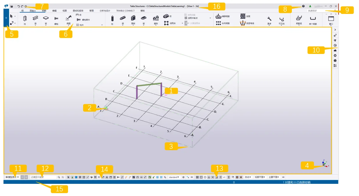
For clarity, the software interface is divided into 16 key sections:
1. This area displays your created model. By default, new models include a grid.
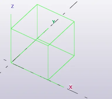
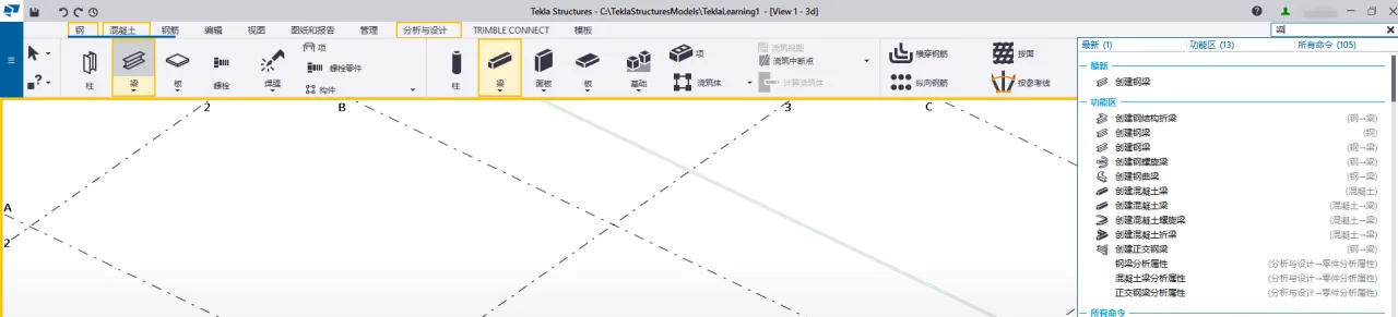
2. The green cube icon represents the global coordinate system, located at the origin (x=0, y=0, z=0). Note that these global coordinates remain fixed and never change.
3. The boxes surrounding the grid define the workspace boundaries. Only objects within this workspace are visible in the view; objects outside exist in the model but remain hidden. You can resize the workspace as needed or temporarily hide the workspace wireframe by pressing Ctrl+Shift and right-clicking to redraw the view.
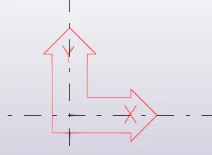
4. The coordinate symbol featuring the x, y, and z axes represents the local coordinate system and indicates the model’s orientation. In the model view, the local coordinate system is shown either as a red arrow or a 3D arrow.

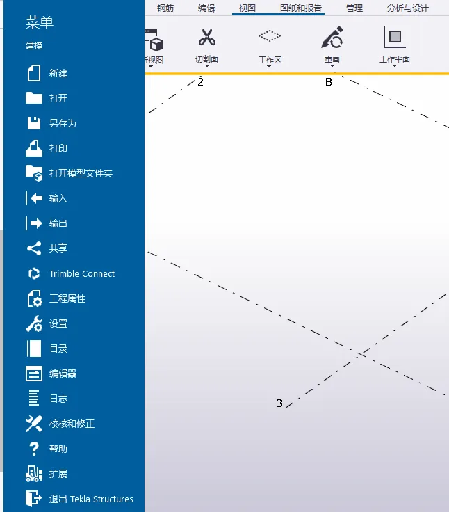
5. The File menu manages your model operations. Here, you can save models, print drawings, import and export models, open directories, edit templates, and perform other tasks.
6. The Ribbon contains the primary commands for creating parts, editing, drawing, and more. It replaces the traditional toolbar collection from older versions, offering a more intuitive interface. Although the ribbon is customizable, the main controls remain largely consistent.

7. The Quick Access Toolbar includes default shortcuts such as save, undo, redo, and undo history. It can be customized to fit your workflow.
8. Your username and a green icon appear in the top-right corner, indicating that you are logged in and your license is active. If a clock icon shows instead, it means the online license connection has been lost. The offline license can be used for up to 72 hours before requiring a new login.
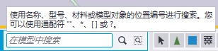
9. Quick Start is a helpful feature that lets you search for commands or dialog boxes directly. If a command exists in the interface, Quick Start will highlight its location, helping users quickly find and learn the available tools.
10. The side pane on the right is divided into seven main sections:
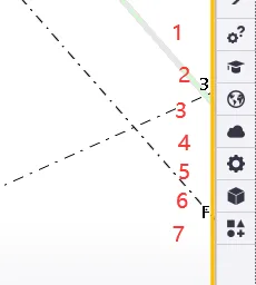
- Custom Queries: Allows you to set your own rules to filter and query specific attributes.
- Instructor: Provides animated and textual guidance to help new users quickly understand Tekla’s functions.
- Tekla Online: Embeds links to Tekla’s resource websites for easy access within the software.
- Point Cloud: Enables attaching point cloud models to Tekla models.
- Property Window: Displays properties of selected parts or components. To view the old property window, select a part, then hold Ctrl and double-click.
- Reference Model: Manages input, display, deletion, and other controls for reference models.
- Applications and Components: Collects built-in nodes and macros. Users can customize components, manage input/output nodes, and define macros.
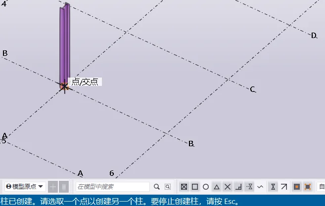
11. The Work Plane Handle toolbar controls the active work plane in your model, allowing you to switch between common work planes, the model origin, or custom work planes.
12. The Search Bar lets you quickly locate objects within the entire model or selected parts. Clicking the search bar opens available search rules.
13. The Snap Switch controls which points you can select when creating objects, such as intersections or vertical feet. It’s important to keep the “Stick to Reference Line” and “Stick to Geometric Line” options enabled at all times to ensure other snaps function correctly. You can enable other snap options as needed.
14. The Selection Switch determines which object types can be selected, making it easier to quickly choose specific parts.
15. The Status Bar guides you through object creation by displaying instructions on how to continue and when to select points. It also shows error messages and indicates the approximate source of any failed creations.
16. This area displays the save path and file name of your model, along with the current view name.
Summary: Since Tekla 2016, the software interface has undergone major stylistic changes. Longtime users of older versions may need some time to adjust, though the core functions remain largely unchanged. The new version introduces many useful features that enhance daily workflows. We recommend spending time to familiarize yourself with the updated interface to improve proficiency.
Note: This article is shared for personal use and not intended for commercial purposes. If any infringement occurs, please contact us promptly. Due to limited experience, errors may exist—feel free to leave comments for corrections. We hope this information proves helpful.


Must log in before commenting!
Sign Up