Source: BimLearning

Tekla Structures uses two main types of coordinate systems: the global coordinate system and the local coordinate system.
The global coordinate system is represented by a bright green cube visible in the model view. Meanwhile, the local coordinate system appears in two forms within the view: a red XY axis plane with arrows, and a 3D arrow located at the lower right corner of the view, as illustrated below.
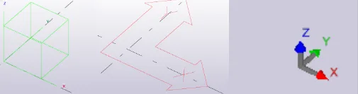
1. Global Coordinate System
The global coordinate system is fixed at the origin point (x=0, y=0, z=0). It is static and cannot be altered. It is recommended to keep your model close to the global coordinate system to maintain accuracy, as positioning the model far from the origin can reduce capture precision.
2. Local Coordinate System
The local coordinate system, also known as the work plane, plays a significant role in various modeling operations such as copying, moving, and mirroring. Unlike the global system, the local coordinate system can be modified.
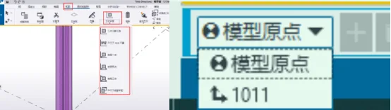
You can adjust the local coordinate system through the ribbon menu by selecting View > Work Plane. Additionally, you can align the work plane with the model origin using the work plane handle tool located at the bottom left corner of the view, or switch to other preset work planes, as shown below.
Note: Proper use of the local coordinate system is essential, as it directly impacts the efficiency of your modeling work. Familiarizing yourself with its functions and patterns will greatly enhance your understanding and workflow.


Must log in before commenting!
Sign Up