Introduction to Design Tables
We are all familiar with the CATIA parts catalog shown below.
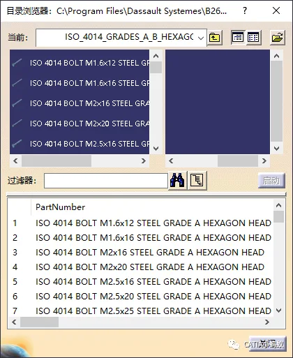
This parts library includes files that come with the CATIA installation, covering standard components such as bolts, nuts, screws, pins, and more. These library files were created by CATIA developers using design tables. Both the design tables and related models are located in the CATIA installation directory. You can find them by navigating to:
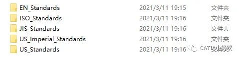
Installpathwin_b64startupcomponentsMechanicalStandardParts
This directory contains parts following European, Japanese, American, and ISO standards, among others.
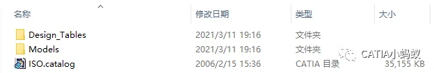
Opening an ISO_Standards folder reveals the iso.catalog file, along with folders for model data and corresponding design tables. Each design table corresponds to a specific model.
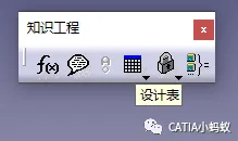
Using the Knowledge Engineering: Design Table Tool, you can select parameters from the design table within CATIA to dynamically update models and create the desired configuration.
Creating a Design Table
To create a design table, use the Design Table Tool found in the Knowledge Engineering toolbar.
Next, we’ll use length, width, and height as driving parameters to establish a simple catalog.
- Create a rectangular prism by first sketching its base, then extruding it based on the sketch.
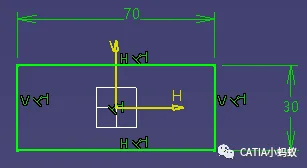
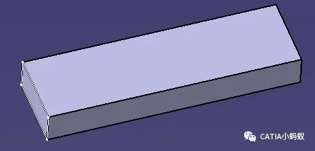
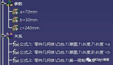
- Define parameters for the three dimensions: a, b, and c.
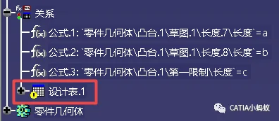
These parameters correspond to the two sketch dimensions and the extrusion length of the rectangular prism. The screenshot below shows the parameters and the three equations f(x) generated after linking them. Once linked, adjusting the parameters a, b, and c will dynamically update the model.
However, to create fixed sets of parameters for multiple specifications of the rectangular model, the design table tool is essential.
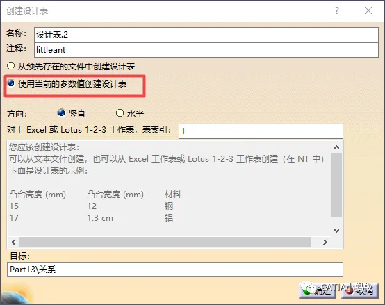
Click the design table icon to open the dialog box, select “Create a design table using current parameters,” and choose the parameters a, b, and c for the table. Export the table as a .txt file to the folder where the rectangular model is saved. Then, using the design table command, add multiple parameter sets to the design table. The design table will appear in the structure tree, allowing you to select different configurations and corresponding model data.
The above summary explains how to create a design table, as previously detailed in our article on establishing a standard parts library. For more information, see:
How to Establish a Standard Parts Library in CATIA? — 200 CATIA Tips Continuously Updated
Design Table Relink (Key Focus of This Article)
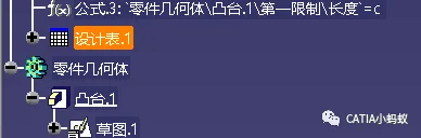
If a design table loses its link, you will no longer be able to select configurations within the structure tree to generate model variants. When this happens, a yellow exclamation mark appears on the design table icon, indicating the link is broken.
To practice this yourself, you can intentionally break the link by saving the 3D model and its design table file in the same folder, then closing both files.
Next, go to the saved folder and change the location or name of the exported design table file (xxx.txt). When you reopen the 3D model, the design table will lose its link, as shown above.
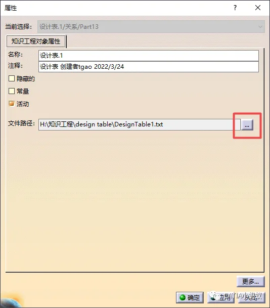
To relink, you need to know the new location of the DesignTable1.txt file.
Select the design table icon in the structure tree, right-click and choose “Properties” to open the properties dialog. Click the browse button (three dots) and navigate to the new location of the .txt file to re-establish the link.
This concludes the explanation on how to relink a design table after it loses its connection.


Must log in before commenting!
Sign Up