Source: CATIA Little Ant

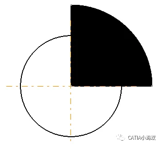
Here is an overview of how to identify reference hole symbols in engineering drawings. Do you remember what you learned about this back in school?

What is the purpose of this hole? According to Baidu Knows, here is the explanation.

Today, we will learn two methods to create benchmark holes in CATIA drawings:
Method 1: Filling (More Complex)
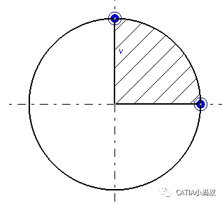
First, draw enclosed areas in the first and third quadrants. Then, use the fill command to fill these areas. Below is the result for the first quadrant only:
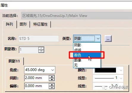
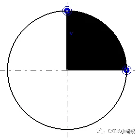
Double-click the filled area to change the fill color to black, as shown below. Repeat the same process for the third quadrant.
Method 2: Using Welding Symbols Cleverly
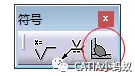
Begin by selecting the welding symbol as shown below:
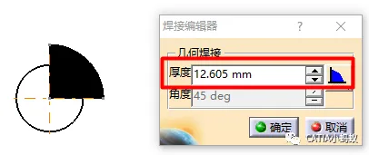
Next, select the upper side of the vertical line and the right side of the horizontal line on the circle’s centerline. This places the weld symbol in the first quadrant.
As seen above, the weld seam extends beyond the circle’s boundary. To fix this, open the welding editor dialog box and adjust the weld seam thickness parameter so the black area fits exactly within the first quadrant of the circle.
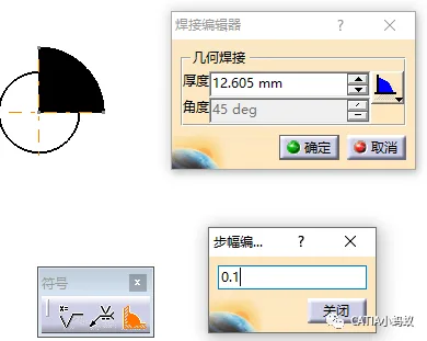
There are two ways to adjust this parameter:
1. Change the increment step of the thickness input box to 0.1mm. This allows precise adjustment using the up and down arrows.
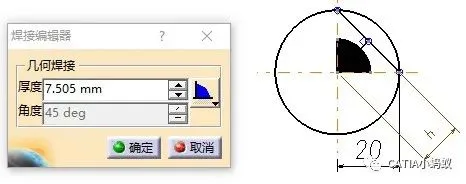
2. Alternatively, enter the weld thickness directly using a formula. For an isosceles right triangle, the height of the hypotenuse is h = √2/2 * r ≈ 0.707 * r. First, determine the circle’s radius. To fill the first quadrant of the weld seam, the thickness parameter should be 0.707 × 20 = 15mm.
That concludes a brief introduction to these two methods for creating benchmark holes in CATIA engineering drawings.


Must log in before commenting!
Sign Up