This article references the 2018 thesis Towards Digitalization of Building Operations with BIM from the Berlin Institute of Technology in Germany. It provides a mid-length overview of digital data collection workflows in building operations.
Introduction to the Previous Context
In our previous article, “Digitizing Building Operations with BIM”, we discussed topics including Building Information Modeling for the Whole Life Cycle Operation Stage of Buildings and the BIM-FM Research Project Discussion. This article focuses on analyzing workflows for digital data collection at project completion, covering data acquisition, processing, and usage methods.
Workflow Analysis: Digital Data Collection for Project Completion
Methods for Acquiring Point Cloud Data
Various technologies exist to capture existing building information. Traditional semi-automatic measurement methods are time-consuming and labor-intensive. Currently, the most popular techniques are ground-based 3D laser scanning and unmanned aerial vehicle (UAV) surveys.
Ground 3D laser scanning offers fast, precise point measurements and enables surveyors to collect data over distances ranging from one to two kilometers, depending on the scanner type (short, medium, or long-range). The outcome is a dense, accurate point cloud, where each point contains x, y, and z coordinates derived from the laser beam’s travel distance.
Drone-based data collection can utilize three approaches: LiDAR, video, or photographic capture. Each method has distinct advantages and limitations and can provide point cloud data either directly or indirectly. This study focuses on photographic data obtained using high-end cameras mounted on drones (also called flight platforms) capturing aerial images of selected building sections. These photos are processed through photogrammetry to generate point clouds, though their accuracy and density are generally lower than ground 3D laser scans.
Additionally, Google Tango technology was tested on a mobile phone to capture point cloud data directly. While results vary in terms of point density and accuracy, this method is limited to a 4-meter capture range.
Point Cloud Data Collection and Processing
The key stages of digital data collection remain consistent regardless of the chosen acquisition method. Figure 2 illustrates detailed subprocesses, time consumption, and critical factors, along with point cloud usage scenarios (see Chapter 3.3).
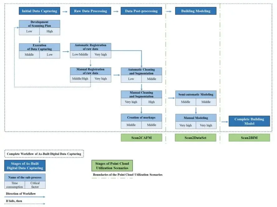
Figure 2: Overall workflow and point cloud utilization scenario for completed digital data collection.
Initial Data Collection
During the initial phase, correctly positioning the detection equipment is paramount. Although this planning requires minimal time, it ensures that raw data overlap remains low (around 25-30%), facilitating successful subsequent processing. For 3D laser scanners, placing the device between door openings helps link different building areas. Similarly, aerial photos captured by drones must include overlapping building points to maintain data continuity. While data collection time is moderate in the overall workflow, precise equipment placement reduces the time needed for numerical data acquisition.
Raw Data Processing
The second phase involves aligning raw data based on overlapping regions to generate a unified, registered point cloud. This can include merging data from different capture methods (see Figures 3 and 4).
Registration can be automated or manual, depending on the target points and overlap quality. Automated registration requires significant data overlap (>55-60%) and is less labor-intensive. Manual registration is necessary when overlap is lower, when building parts are similar in height (e.g., different stair levels), or when integrating data from diverse methods. This step is critical for successful point cloud creation, with time requirements varying based on data volume and overlap extent.
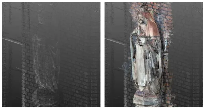
Figure 3: St. Hedwig Hospital example showing integration of point clouds from different measurement techniques (left: 3D laser scanning; right: 3D laser scanning combined with Google Tango technology).
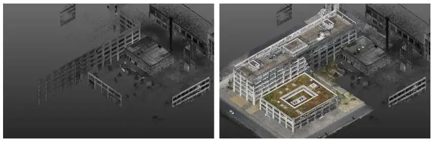
Figure 4: Wilhelminenhof HTW Park pilot test showing point cloud integration from different technologies (left: 3D laser scanning; right: 3D laser scanning combined with drone measurement).
Data Post-Processing
The third phase involves removing noise from the point cloud and segmenting the remaining data into smaller, meaningful parts (see left side of Figure 5). This can be performed automatically or manually. While automatic cleaning and segmentation reduce manual effort, the results often remain unsatisfactory. For example, some unwanted points such as human contours may remain after automatic cleaning. Although automatic segmentation can separate clusters like poles, vegetation, and ground, it often fails to isolate relevant building parts as individual segments (middle of Figure 5). Thus, significant manual cleaning and segmentation are necessary to achieve the desired outcome (right side of Figure 5).
This stage is essential to improve the visibility of geometric information and reduce computational demands for processing large datasets. Manual cleaning and segmentation are critical to avoid handling overly large point clouds during architectural modeling. Furthermore, assigning consistent naming schemes aligned with existing CAFM systems greatly assists facility managers (see Chapter 3.3.2). Tags can also be added to smaller segments to correspond with CAFM naming conventions (see Chapter 3.3.3).
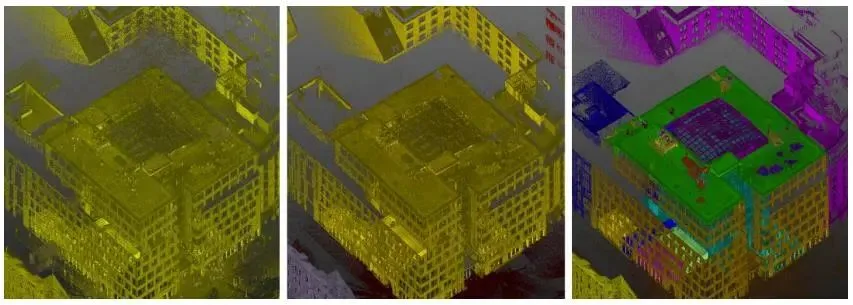
Figure 5: Processing status of point cloud data in the Ndehaus case (left: raw data; middle: automatically processed; right: manually processed).
Architectural Modeling
In the final phase, a digital building model is created from the processed point cloud data. This can be done semi-automatically or manually. Semi-automatic modeling tools convert point cloud data into parameterized building objects (native Revit family objects), significantly reducing manual effort. These tools automatically identify walls, openings, beams, columns, and MEP piping systems (see left side of Figure 6).
After automatic identification, manual adjustments are necessary to confirm or correct element recognition and to connect separately identified components. This tool greatly reduces the manpower required for model creation. While the key factors here are moderate and do not affect overall workflow success, they substantially improve global time efficiency.
Because semi-automatic models tend to be less precise, further manual refinement is required to achieve high accuracy. This involves detailed modeling of individual building objects, which is time-consuming but essential for high-quality information (see right side of Figure 6).
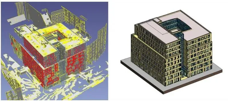
Figure 6: Architectural modeling in the Ndehaus case (left: automatic modeling; right: manual modeling).
Using FM to Obtain Completion Data
Scan to BIM
The traditional approach to applying point clouds is through Scan to BIM, where building model objects are defined based on point cloud segments and existing planes. Once the model is complete, the point cloud data becomes redundant.
At first glance, modeling every detail of the building is advantageous, as the architectural model contains all relevant geometric and non-geometric information from the original data. This means the point cloud dataset is fully utilized and can be discarded after model creation.
However, this approach has drawbacks: it remains time-consuming and labor-intensive, and building models with excessive detail can suffer from performance issues. Additionally, maintaining such detailed models poses challenges.
Scan to Dataset
A key project goal is to reduce the workload of creating digital building models by limiting BIM object accuracy to a satisfactory level. This requires a more general use of point clouds, referred to as Scan to Dataset.
Here, the original point cloud is displayed alongside the building model without converting into parameterized building elements. This approach allows the building model to start with lower accuracy, representing objects graphically as lightweight BIM objects.
The point cloud supplements missing information in the building model. For FM purposes, missing or incomplete building elements can be visualized by identifying them clearly in the point cloud, defining and naming line segments in detail, and adding tags.
This method enables FM teams to quickly locate incomplete building details, reducing the time and effort required to complete the building model. It also lessens hardware demands. Developers can later refine the building model using both the model and point cloud dataset as needed.
Scan to CAFM
To further reduce workload, a third option involves directly extracting data from the point cloud without creating a digital building model. Relevant FM information is retrieved from the point cloud and transmitted directly to the CAFM system database.
Point cloud data not only provides visualization but also allows numerical measurement, labeling, and image linking of each captured point. This capability can reduce traditional on-site measurement efforts.
However, quality limitations exist. For example, scanning resolution is often insufficient to read text on equipment panels, limiting analysis of certain items. Nonetheless, inventory items like tables and chairs, as well as some MEP equipment (e.g., pumps, motors), can be identified accurately. Measurements such as distances between walls and equipment locations can be used to populate CAFM database entries.
On-site testing demonstrates that using point clouds in this manner shows promise by reducing repeat site visits and overall workload. Although some data retrieval requires manual or automatic intervention, the amount of available information remains limited but valuable.


Must log in before commenting!
Sign Up