This article is from the WeChat official account: Xiao Jiang said BIM.

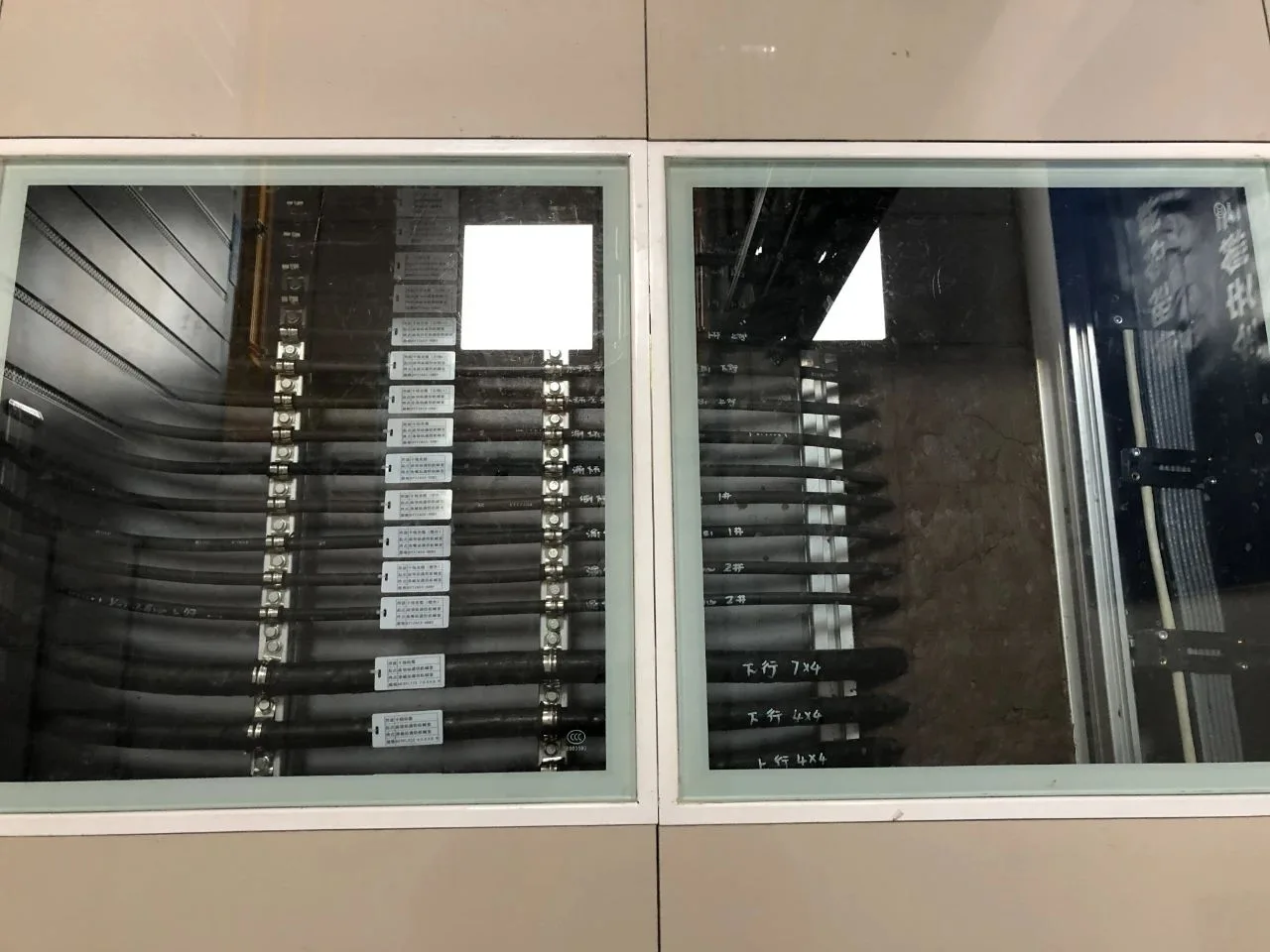
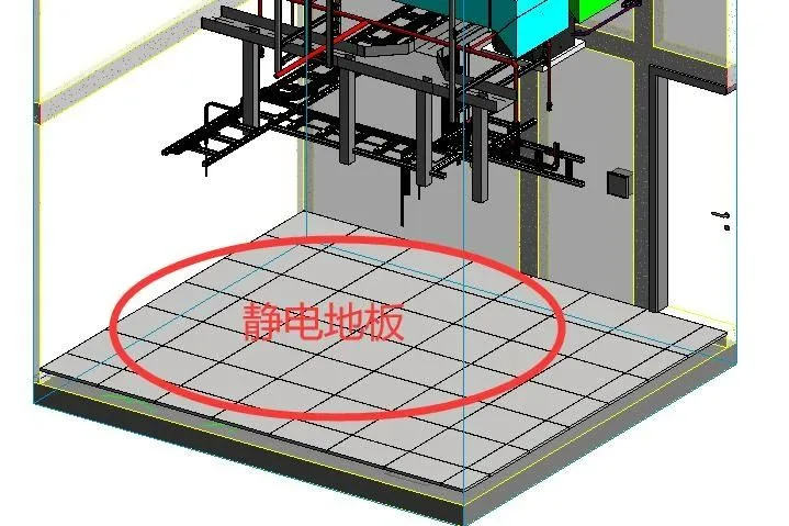
Recently, a colleague asked how to model a glass electrostatic floor in a communication room. There are several ways to approach this challenge:
1. First, create the electrostatic floor and leave gaps where the glass panels will be placed. Then, design a standard model family for a single glass floor panel and insert each piece individually into those gaps, adjusting the height as needed. This method is versatile and widely applicable. In most modeling tasks, creating shape families solves nearly all object modeling challenges. Drawing families is often a backup when other solutions are unavailable, as simple appearance-only families lack flexibility.
2. Alternatively, use curtain wall panel tools to create the glass panels.
In a previous section titled “On the Method of Building a Floor Tile Model,” we discussed how curtain wall panels are applied to tile layouts. Typically, grid-like shapes—such as glass curtain walls—are built using curtain wall panels. First, define the number of horizontal and vertical panels in the grid, which simplifies management. Tiling involves setting the tile dimensions, creating a tile family, and placing these tiles as panels over a large area.
Similarly, for glass flooring, start by drawing the static floor in the computer room, then replace selected floor panels with glass panels.
Below is a step-by-step guide to modeling glass flooring. Beginners may find this complex, as curtain wall panels can be more challenging than other tools. I recommend following the illustrations and practicing multiple times to get comfortable.
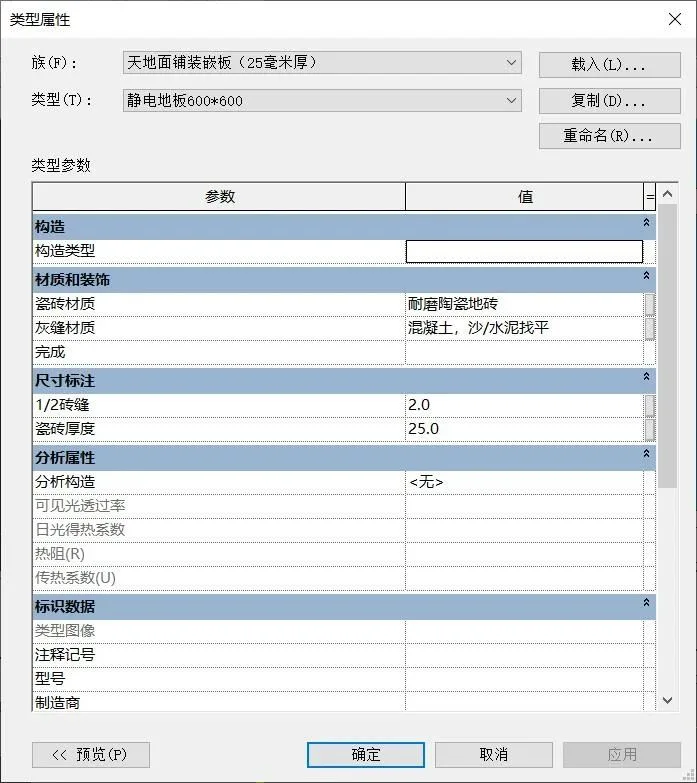
1. Duplicate a ceiling paving panel family and rename it “Electrostatic Floor 600 x 600.” Open its properties and set the “1/2 Brick Seam” to 2 millimeters and the tile thickness to 25 millimeters. This creates the electrostatic floor panels.
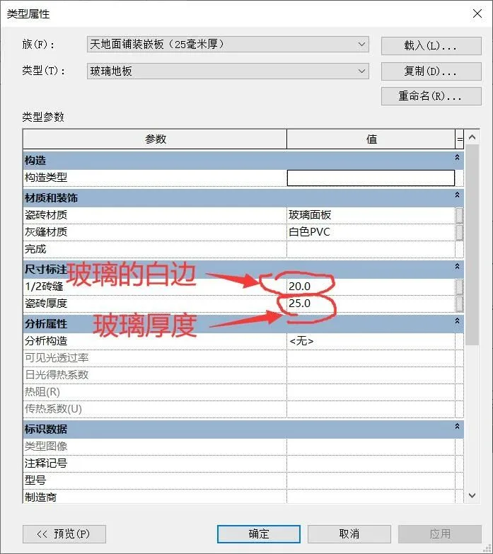
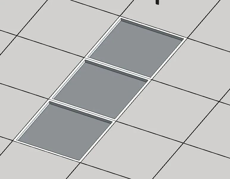
2. Next, duplicate a surface paving panel family and rename it “Glass Floor.” Adjust its properties by setting the “1/2 Brick Seam” to 20 millimeters (which represents the white edge around each glass piece) and the tile thickness to 25 millimeters (the glass thickness). Change the material from “ceramic tile” to glass, and replace the “gray joint material” with white plastic. This step prepares the glass floor panels.
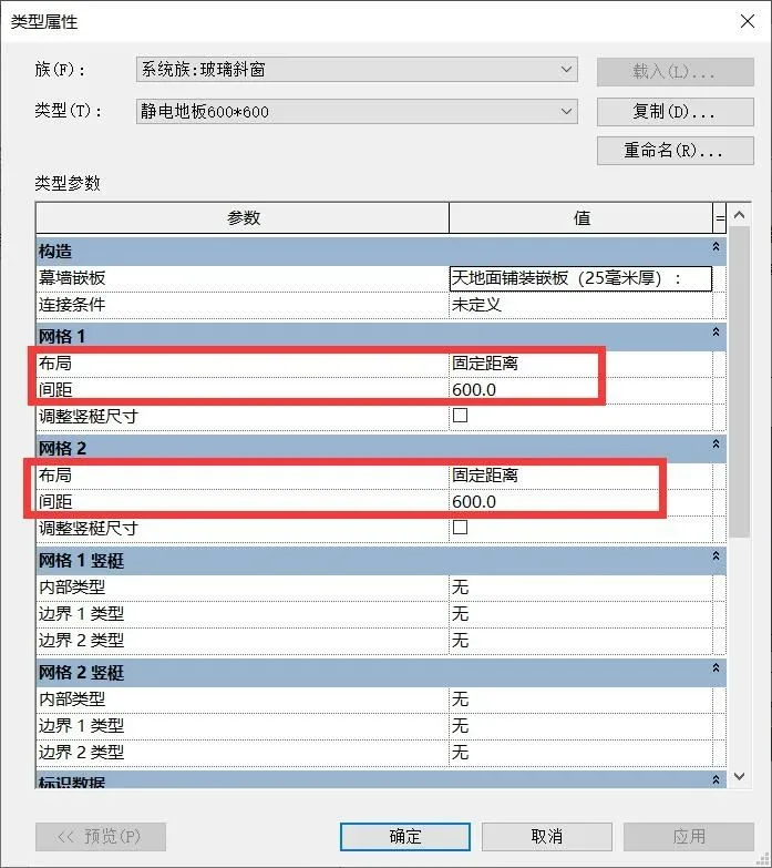
3. Copy a sub-item from “Glass Sloping Windows” in the Project Browser and rename it “Electrostatic Floor 600 x 600.” Change the spacing between “Grid 1” and “Grid 2” to 600 millimeters in the type properties. Then, set the “Curtain Wall Panel” option to “Electrostatic Floor 600 x 600.”
4. With these preparations complete, start drawing the static floor. In the computer room’s plan view, use the “Trace Roof” tool to outline the floor boundary (inner wall line). Change the roof type to “Static Floor 600 x 600,” then adjust the floor to the correct height.
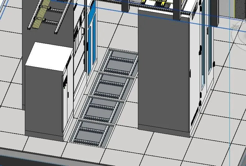
5. Now, replace selected floor panels with glass panels. Hover over the desired position and press the TAB key to highlight the area. Select it, unlock it, and from the properties dropdown menu, choose “Glass Floor.” The panel will become transparent glass. Replace as many panels as needed; here, we replace four. Then, place a wire rack beneath the glass to see if it closely matches the intended look.


Must log in before commenting!
Sign Up