Revit’s MEP projects are designed to implement building plumbing and drainage systems through both physical and logical connections.
First, it’s important to understand the concept of pipeline systems. Revit’s piping system family comes with 11 predefined piping system types: “Circulating Water Supply,” “Sanitary Equipment,” “Domestic Hot Water,” “Domestic Cold Water,” “Ventilation Holes,” “Wet Fire Protection System,” “Dry Fire Protection System,” “Pre-action Fire Protection System,” “Other Fire Protection Systems,” and “Other.”
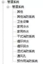
Predefined pipeline system types in the software
Specific devices assign particular system types to pipelines depending on the component type. If the predefined pipeline system lacks the system type you need, you can duplicate an existing system type and modify its properties accordingly.
It is necessary to recreate pipeline types based on the specific pipeline categories designed for your project, such as water supply, hot water, fire water, and so on.
After creating the pipeline type, you may find that its properties do not fully align with the design intent of the project drawings. At this stage, you should reset the routing system configuration.
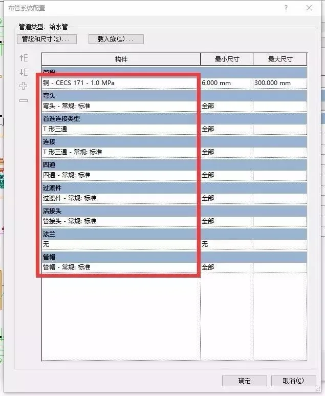
Piping system configuration dialog box
Since pipe types vary from project to project, you should first identify the materials and connection methods specified in the design drawings. Then, adjust these settings individually in the Pipe Layout System Configuration before creating pipe segments.
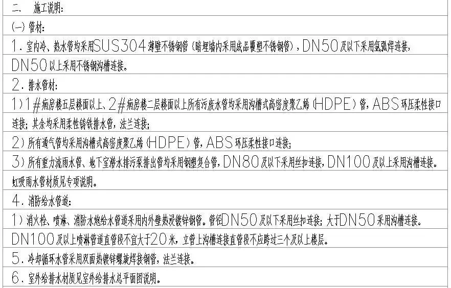
Pipe specifications according to design drawings
If the required materials are missing from the pipe sections, you can create them based on original pipe sections in the Pipe Section and Size dialog box.
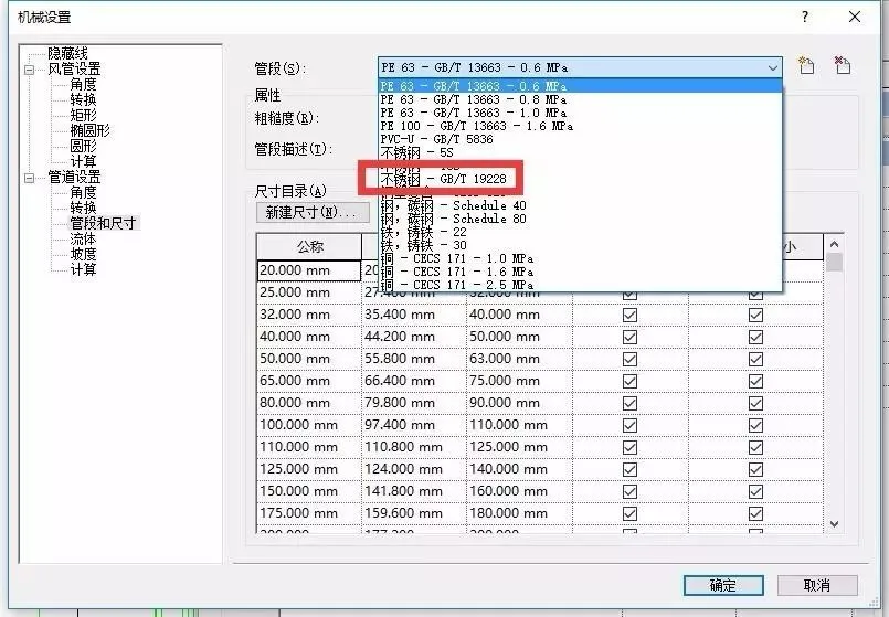
If the nominal diameter you need is not available, you can add new sizes in the New Size dialog box.
Once your pipeline types are set, you can import your drawings into Revit by layers. To improve performance, consider turning off any unused layers before importing.
When drawing pipe segments, follow the three-step method: selecting commands, setting parameters, and drawing pipe segments.
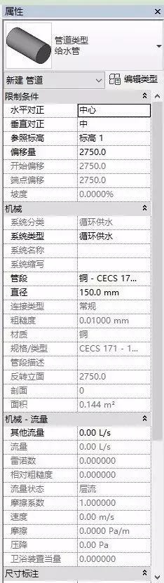
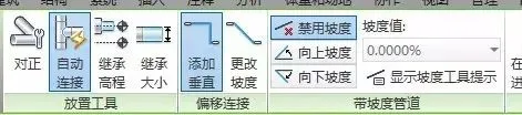
The Set Parameters step involves configuring various pipe segment attributes such as alignment, reference elevation, offset, and system type. It’s also crucial to check whether the pipe segment has a slope. If so, be aware that the slope requirements vary depending on the pipe diameter.


Must log in before commenting!
Sign Up