China Zun is situated on the Z15 plot in Beijing’s central business district. It is bordered by Jinhe Road to the east and west, planned green space to the south, and Guanghua Road to the north. Standing as the tallest landmark in Beijing, China Zun’s development began with land acquisition in September 2012, and official construction started on July 29, 2013.
On June 8, 2014, China Zun was honored as the “Best Contemporary Chinese Architecture” among the “Ten Contemporary Chinese Buildings.” The underground structure was fully covered by December 10, 2014. By August 18, 2016, the China International Trade Center section, above 330 meters, reached the highest point in Beijing. On November 9, 2016, China Zun surpassed 400 meters in height. In the early hours of April 28, 2017, the building reached 104 floors and exceeded 500 meters, establishing itself as a new capital landmark and the tallest building in Beijing (see Figure 2).

Figure 2: Legend of China Zun Building
Architectural Layout
Building 2 is an industrialized residential structure featuring two underground levels and 27 floors above ground. It covers a total area of 11,478 square meters, with each floor approximately 395.05 square meters and a floor height of 2.9 meters. The building includes two staircases and accommodates four residents per floor, with the staircases designed as scissor stairs. Floors 2 through 6 feature cast walls with laminated top plates, while floors 7 to 27 use prefabricated walls also topped with laminated plates.
The construction employs standardized components: 22 exterior wall panels, 13 interior wall panels, 46 laminated panels, 11 prefabricated cantilever elements, and 10 other prefabricated parts, totaling 102 components. The exterior panels are extruded sandwich control panels made from polystyrene boards. The heaviest components weigh up to 8 tons, stairs weigh 4 tons, and concrete consumption totals 64.46 cubic meters.
The innovative engineering technologies and measures applied throughout the project’s construction are summarized in Table 1.
BIM Application
(1) Design Deepening Phase
Traditional site layouts rely on CAD floor plans, which often fail to communicate precise site information to non-professional stakeholders such as clients, leading to inconsistent interpretations during construction. BIM technology uses a three-dimensional information model to create a visualized site layout, accurately reflecting the construction and decoration phases in 3D. Figure 3 illustrates the 3D visualization of the safety passage and steel processing shed for this project.
Another critical aspect is earthwork balance. REVIT software integrates actual site elevation data from the Geological Survey Bureau and the design institute to generate a realistic 3D topographic map (see Figure 4a). Using this data, a site leveling model is created, and simulations are performed to analyze site grading, resulting in a BIM site alignment diagram (Figure 4b). Covering an area of 41,888.3 square meters with a building footprint of 18,635 square meters, the earthwork comparison plan is shown in Figure 4c. Through BIM optimization, excavation and backfill strategies for two earthwork projects were simulated, reducing clay construction costs by nearly 400,000 yuan.
Table 1: Engineering Innovation Technologies and Measures
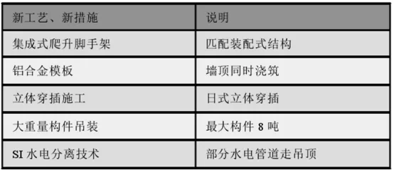
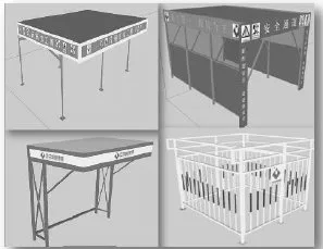
Figure 3: 3D Visualization of Site Layout
Following this, the project advanced to detailed component design involving production and design teams. Prefabricated wall groove designs were refined to specify the positions of inclined supports for inserting sleeves, template locations and fixing holes, circular keel fixing points, component groove structures, and the integration of wooden exterior window tiles and reserved holes. For laminated prefabricated boards, grooves were designed for flue gas openings, built-in suspension points, prefabricated electrical boxes, as well as edges and grooves. BIM software integrated various professional models, enabling comprehensive hole counts and visual verification of unsuitable reserved holes. This allowed for design modifications to correct inappropriate openings without disrupting overall pipeline layouts.
In current civil engineering practice, steel reinforcement sampling is often managed by work teams without sufficient professional oversight, resulting in poor communication between clients and contractors and lack of process control. This frequently leads to excessive steel usage before project completion and weak contractual controls. In this project, BIM technology was strictly applied to advanced steel reinforcement management. Through manual sampling mastery and the use of Glodon steel reinforcement 3D modeling and sampling software, the project aimed to achieve 3D sampling-guided design.
Post-BIM optimization, HRB400E was selected as the reinforcement material for Column 2#, with maximum diameters of 28mm and 35mm. Figure 5 presents schematic diagrams of the two cylindrical reinforcement components, detailing their construction.
(2) Component Production Stage
Considering the manufacturing process, transportation requirements, and temporary construction measures for Building 2, BIM allows real-time updates to component model information within the building model. This flexibility improves component layout, enhances model consistency, and supports various stages of construction. Structural components include doors, windows, columns, beams, and wall panels. The software provides necessary attribute information for components at every stage, as summarized in Table 2.
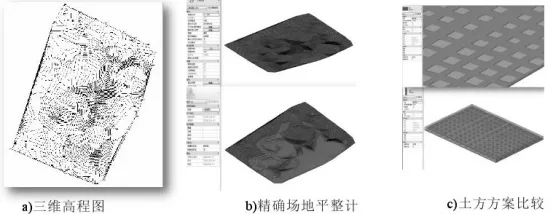
Figure 4: Comparison of Earthwork Plans
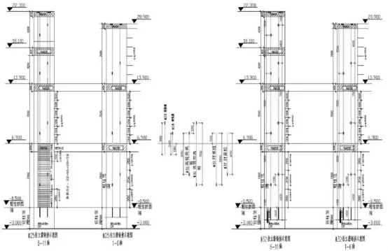
Figure 5: Reinforcement Detail Information
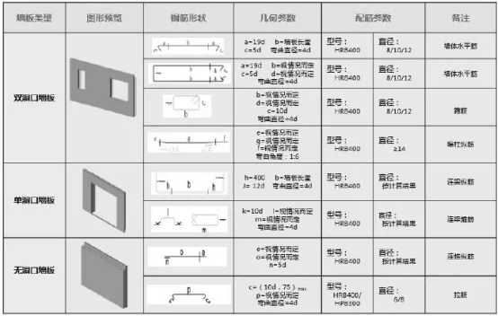
Table 2: Attribute Information of Wall Panel Components
Progress Management During Construction
During construction, the project team developed an “Interlocking Construction Cycle Table” aligned with the overall network construction schedule. This effectively coordinated structural construction, pre-decoration, fine decoration, and external drainage work, ensuring precise sequencing and coordination among subcontractors. The construction plan was regularly updated and visualized on-site, enabling multi-process, multi-subcontractor management. Daily progress confirmation allowed for orderly contract execution and accurate project implementation.
Source: Science and Technology Innovation 2021.28
Author: Liu Hongyan (Guangzhou Urban Construction Vocational School)
For educational and communication purposes only. If any infringement occurs, please contact us for removal.


Must log in before commenting!
Sign Up