Question: How can you differentiate between cable trays and duct legends in a comprehensive pipeline section diagram?
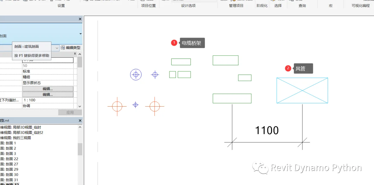
In pipeline cross-section diagrams, both cable trays and air ducts are typically represented with boundary and interior lines marked by an “X”. This makes it impossible to tell whether a pipeline element is a tray or a duct based solely on this legend.
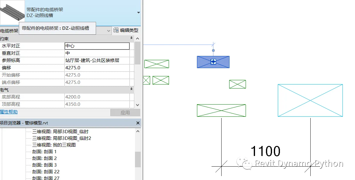
Default display style for cable trays in profile views:
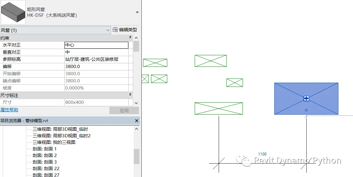
Default display style for cross-sectional air ducts:
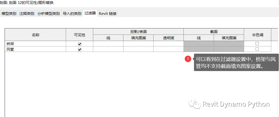
In filter settings, it is not possible to differentiate cable trays from ducts using patterns; only color distinctions are available. However, this approach is ineffective for black and white printed drawings.
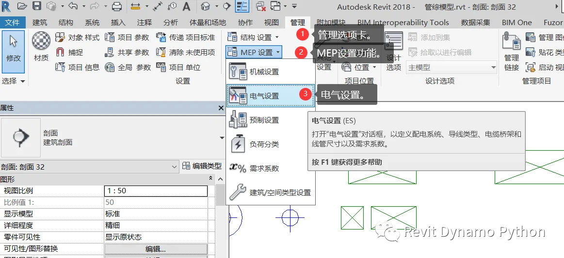
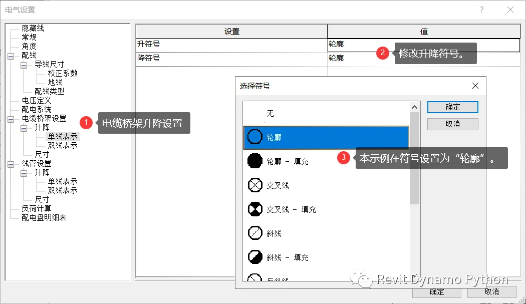
To adjust the display style for cable trays or ducts in section views, the key is to modify the “rise” and “fall” legends.
The “rising” and “falling” symbols for cable trays are controlled within electrical settings and default to a “four-way” style. You can customize these symbols to distinguish cable trays from ducts by selecting different built-in Revit patterns.
Within the electrical settings, the double-line representation is applied to cable tray risers. In this example, the symbol style is set to “outline”.
After these modifications, the cable tray and duct can be clearly distinguished within the section view.
Similarly, air ducts can also have their section display legends adjusted by setting rise and fall symbols within the duct system. This example is not shown here in detail.


Must log in before commenting!
Sign Up